Automatic production line of total heat exchange core, and cutting and conveying structure thereof

A technology of automatic production line and full heat exchange core, applied in metal processing and other directions, can solve the problem of troublesome film suction process, and achieve the effect of high degree of automation, high blanking efficiency and good blanking effect.

Active Publication Date: 2021-01-22
绍兴百立杰环保科技有限公司
View PDF5 Cites 5 Cited by
  • Summary
  • Abstract
  • Description
  • Claims
  • Application Information

AI Technical Summary

Problems solved by technology

[0005] The applicant believes that: after the cutting mechanism cuts the diaphragm, the diaphragm is still adhered to the complete diaphragm, and the

Method used


Image

  • Automatic production line of total heat exchange core, and cutting and conveying structure thereof
  • Automatic production line of total heat exchange core, and cutting and conveying structure thereof
  • Automatic production line of total heat exchange core, and cutting and conveying structure thereof

Examples


Embodiment Construction

[0047] The following is attached Figure 1-12 The application is described in further detail.

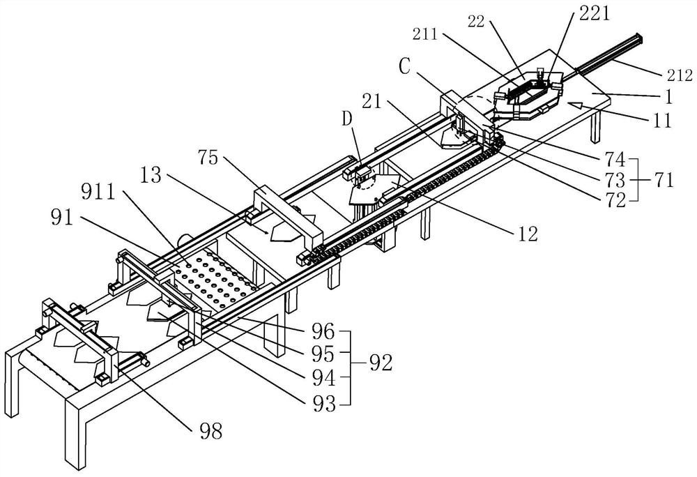
[0048] The embodiment of the present application discloses an automatic production line of a total heat exchange core and its cutting and conveying structure. refer to figure 1 , including a frame 1, the frame 1 is provided with a blanking station 11, a stacking platform 12, a film placement station, a conveyor belt 91, a conveying mechanism 92, an auxiliary lifting mechanism and a cutting mechanism 98.

[0049] The blanking station 11 is provided with a blanking mechanism and a first conveying mechanism 71, the stacking platform 12 is arranged between the blanking station 11 and the diaphragm placement station, and a The second delivery mechanism 75.

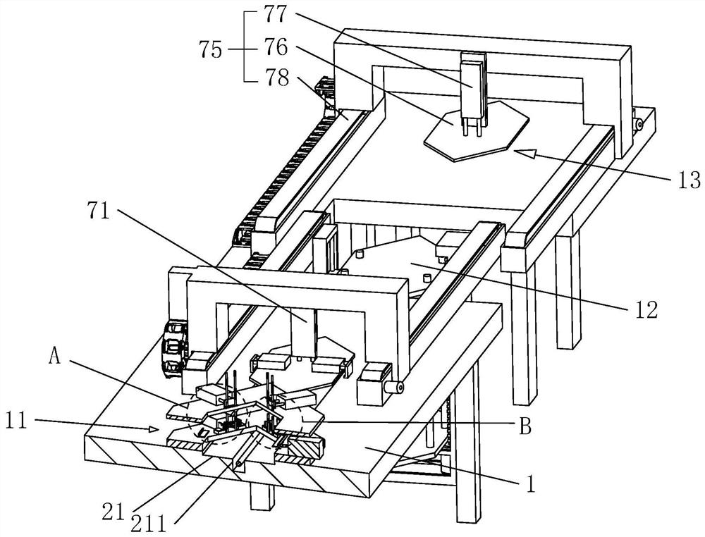
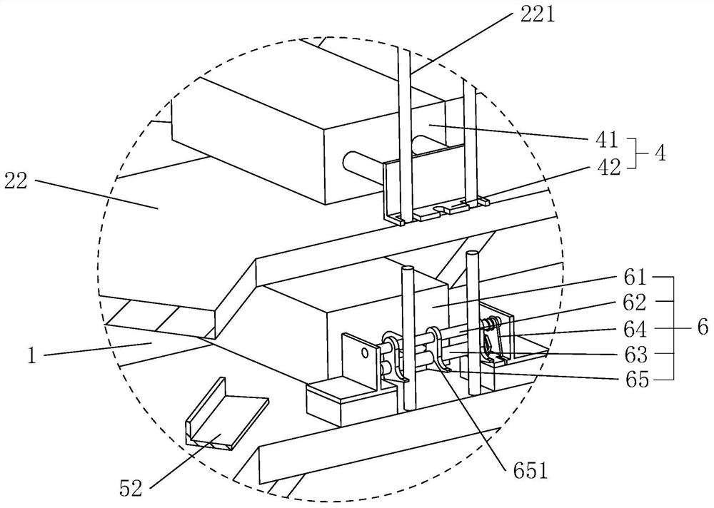
[0050] like figure 2 , image 3 as well as Figure 4 As shown, the blanking mechanism includes a blanking trough 21 , a positioning frame 22 , a first supporting mechanism 3 , a second supporting mechanism 4 , a third supporti...


PUM


Abstract

The invention relates to a cutting and conveying structure of an automatic production line of a total heat exchange core. The cutting and conveying structure comprises a rack, a conveyor belt used forplacing and conveying a diaphragm to be cut, a cutting mechanism arranged on the rack and used for cutting the diaphragm, and a conveying mechanism used for taking out the cut diaphragm; the conveying mechanism comprises a conveying sucker, a first driving part for driving the conveying sucker to move in the width direction of the rack, a second driving part for driving the conveying sucker to move up and down, and a third driving part for driving the conveying sucker to move in the length direction of the rack, and an auxiliary lifting mechanism is arranged on the rack, and comprises a jet head; air holes are formed in the surface of the conveyor belt, and the jet head is arranged on the rack, and located below the diaphragm; and the jet head is connected with an air source, and used forblowing air to the bottom surface of the diaphragm. The cutting and conveying structure has the effects of assisting the conveying sucker in sucking the cut diaphragm, and reducing the probability ofpulling the whole diaphragm during diaphragm sucking.

Description

technical field [0001] The present application relates to the technical field of production of total heat exchange cores, in particular to an automatic production line of total heat exchange cores and its cutting and conveying structure. Background technique [0002] A total heat exchanger usually refers to a fresh air, exhaust air ventilation equipment that contains a full heat exchange core. [0003] The total heat exchange core of the existing plate-type total heat exchanger includes flow channel plates arranged at intervals from top to bottom and heat exchange paper arranged between adjacent flow channel plates. During processing, the stacked flow channel plates are removed one by one, and then the flow channel plates are manually placed on the stacking table, and then the heat exchange paper (hereinafter referred to as the diaphragm) is placed on the flow channel plates for alternate stacking. . [0004] The heat exchange paper is cut on the entire membrane by a cutti...

Claims


Application Information

Patent Timeline
IPC IPC(8): B26F1/38B26D7/32
CPCB26F1/38B26D7/32B26D2007/322
Inventor 周代烈张家兵黄鸿鑫徐思扬
Owner 绍兴百立杰环保科技有限公司
Why Eureka
Try Eureka