Eureka AIR delivers breakthrough ideas for toughest innovation challenges, trusted by R&D personnel around the world.

Numerical control aerodynamic shuttle loom

A gas-powered loom technology, applied in looms, weaving, textiles and papermaking, etc., to achieve the effects of reduced friction, effective control, and simple actions

Pending Publication Date: 2021-01-22
山东军冠纺织有限公司
View PDF0 Cites 0 Cited by
  • Summary
  • Abstract
  • Description
  • Claims
  • Application Information

AI Technical Summary

Problems solved by technology

[0003] In order to solve the above technical problems, the present invention provides a shuttle picking pneumatic device for braking, which is simple in action and effective in control. When the multifunctional air floating shuttle swings left and right, the shuttle picking pneumatic device moves in coordination, reducing errors and reducing noise. Numerically Controlled Air Powered Shuttle Loom with Reduced Shuttle Thread Breakage

Method used


Image

  • Numerical control aerodynamic shuttle loom
  • Numerical control aerodynamic shuttle loom

Examples


Embodiment Construction

[0012] The specific implementation manners of the present invention will be further described in detail below in conjunction with the accompanying drawings and embodiments. The following examples are used to illustrate the present invention, but are not intended to limit the scope of the present invention.

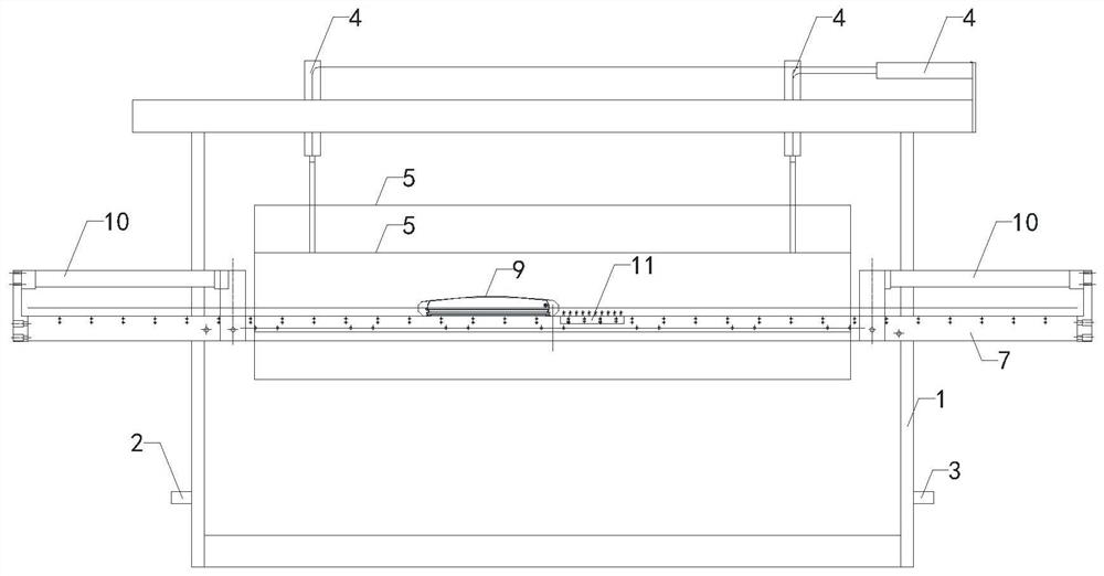
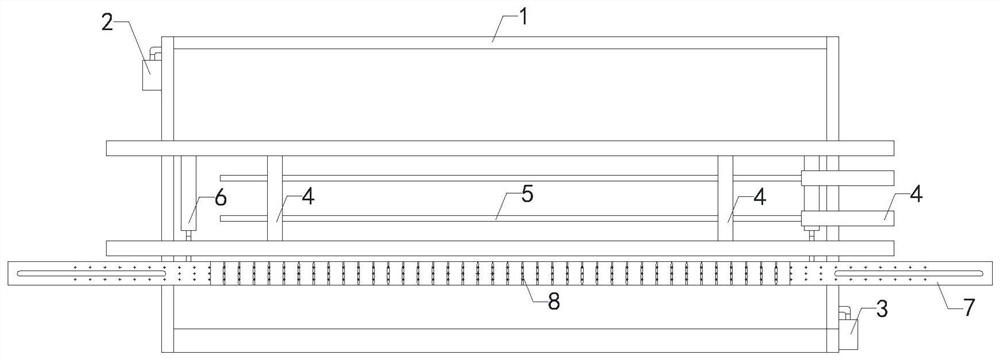
[0013] Such as Figure 1 to Figure 2 As shown, a kind of numerical control air power shuttle loom of the present invention comprises body 1, let-off pneumatic device 2, coiling pneumatic device 3, heald frame opening pneumatic device 4, heald frame 5, weft beating pneumatic device 6, The air-floating guide rail 7, the multifunctional air-floating shuttle 9 and the air-floating shuttle hook 11, the let-off pneumatic device 2 and the coiling pneumatic device 3 are all fixedly installed on the body 1, and the heald frame opening pneumatic device 4 is installed on the top of the body 1, The heald frame opening pneumatic device 4 is provided with a heald frame 5, the beating-u...


PUM


Abstract

The invention relates to the technical field of textile, in particular to a numerical control aerodynamic shuttle loom. The numerical control aerodynamic shuttle loom adopts a shuttle shooting pneumatic device for braking, is simple in action and effective in control; and when a multifunctional air floating shuttle swings left and right, the shuttle shooting pneumatic device moves coordinately, errors are reduced, noise is reduced, and meanwhile the situations of shuttle clamping and yarn breaking are reduced. The numerical control aerodynamic shuttle loom comprises a loom body, a warp let-offpneumatic device, a take-up pneumatic device, a heald frame opening pneumatic device, a heald frame, a beating-up pneumatic device, an air floating guide rail, a multifunctional air floating shuttleand an air floating shuttle hook. The warp let-off pneumatic device and the take-up pneumatic device are fixedly installed on the machine body; the heald frame opening pneumatic device is installed above the machine body; the heald frame is arranged on the heald frame opening pneumatic device; the beating-up pneumatic device is installed on the machine body; a beating-up mechanism is arranged on the beating-up pneumatic device; the air floatation guide rail is transversely installed in the machine body; exhaust holes are formed in the air floatation guide rail; and the multifunctional air floatation shuttle is placed above the air floatation guide rail.

Description

technical field [0001] The invention relates to the technical field of weaving, in particular to a numerically controlled gas-powered shuttle loom. Background technique [0002] A loom is a machine that interweaves two or more groups of yarns at right angles to form a fabric, which is widely used in the field of textiles; the existing loom process usually needs to send warp yarns according to weaving needs , the warp yarn is divided into upper and lower layers to form the mechanism of the shed opening, the mechanism for introducing the weft yarn into the shed opening, and the mechanism for pushing the weft yarn introduced into the shed opening to the weaving opening, so that the fabric forms a specified weft density, and then it is drawn away from the working area and rolled to the cloth roller In the use of existing looms, it is found that traditional textile machinery is mechanically driven, with cumbersome actions, high noise, and is easy to get stuck in the shuttle, resu...

Claims


Application Information

Patent Timeline
Patent Type & Authority Applications(China)
IPC IPC(8): D03D49/10D03D49/42D03D49/20D03C5/00
CPCD03C5/00D03D49/10D03D49/20D03D49/42
Inventor 张常军张铭毓张铭珠杨文水
Owner 山东军冠纺织有限公司
Why Eureka
Eureka Blog
Learn More