A gas pipeline with integrated cooling channel

A technology for cooling channels and gas pipelines, which is applied to jet propulsion devices, machines/engines, rocket engine devices, etc. It can solve problems such as difficulty in quality consistency control, low integration, and long processing cycle, so as to avoid local temperature The effects of excessively high, simplified process, and reduced development cost

Active Publication Date: 2021-10-19
XIAN AEROSPACE PROPULSION INST
View PDF7 Cites 0 Cited by
  • Summary
  • Abstract
  • Description
  • Claims
  • Application Information

AI Technical Summary

Problems solved by technology

[0003] In order to solve the technical problems of the existing gas pipeline with cooling structure, such as long processing period, complex process, high cost, difficulty in quality consistency control and low integration, the present invention proposes a gas pipeline with integrated cooling channel

Method used


Image

  • A gas pipeline with integrated cooling channel
  • A gas pipeline with integrated cooling channel
  • A gas pipeline with integrated cooling channel

Examples


Embodiment Construction

[0041] The present invention will be described in detail below in conjunction with the accompanying drawings.

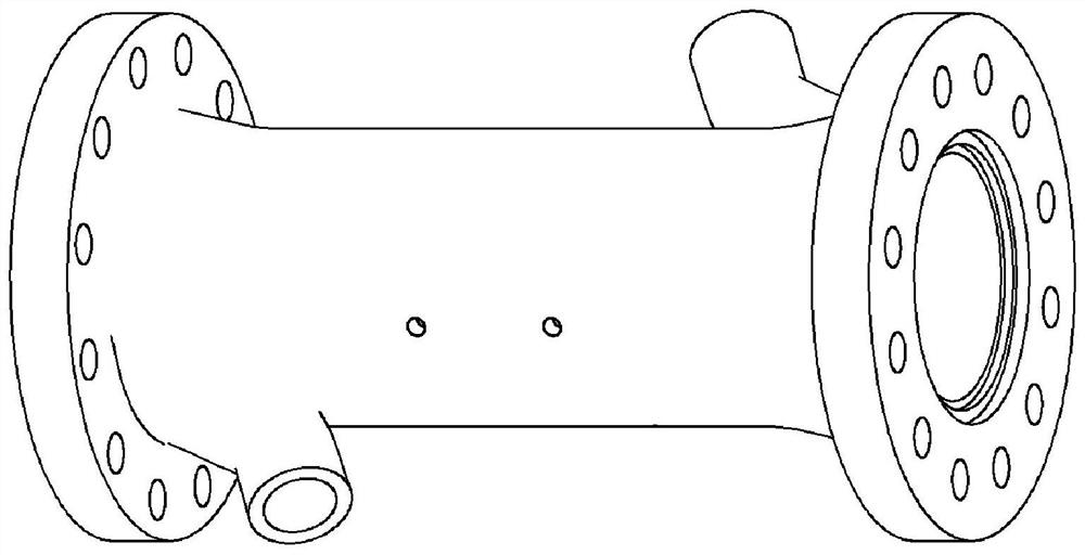
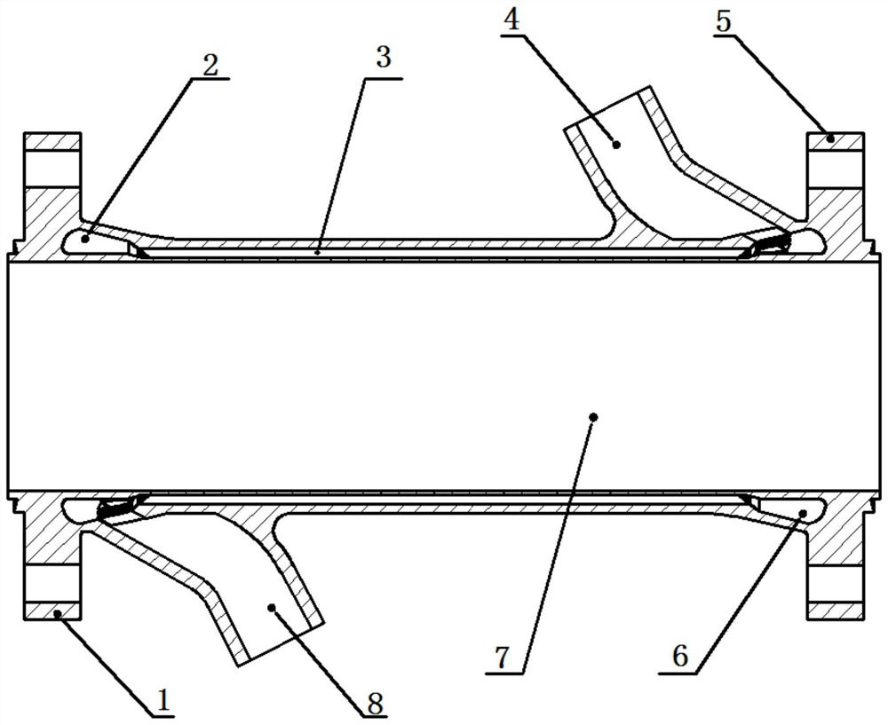
[0042] Such as Figure 1-2 As shown, the gas pipeline of the integrated cooling channel provided by the present invention includes a gas channel 7, a first flange 1 and a second flange 5 respectively arranged at both ends of the gas channel 7, and a gas channel arranged on the side wall of the gas channel 7 The cooling medium inlet pipe joint 4 and the cooling medium outlet pipe joint 8, wherein the cooling medium inlet pipe joint 4 is closer to the second flange 5, and the cooling medium outlet pipe joint 8 is closer to the first flange 1.

[0043] Both the cooling medium inlet pipe joint 4 and the cooling medium outlet pipe joint 8 adopt a gradually expanding form, and the overall shape is like a spout; the cooling water inlet end section of the cooling working medium inlet pipe joint 4 is circular, and the cooling water outlet end section is circular. It is ellipti...


PUM


Abstract

In order to solve the technical problems of long processing period, complex process, high cost, difficulty in quality consistency control and low integration degree of the existing gas pipeline with cooling structure, the present invention proposes a gas pipeline with integrated cooling channel. The invention integrates the cooling channel in the side wall of the gas channel, which simplifies the process and improves the integration of the product; adopts the structural design oriented to the 3D printing process, and realizes the cooling working medium inlet pipe joint and the cooling working medium inlet liquid collection chamber , cooling channels, etc., and the overall unsupported design of the gas pipeline, this structure can meet the overall one-time molding requirements of 3D printing technology, without the need for multi-channel racks, brazing, butt welding and other procedures in the traditional process, product processing and turnover cycle It is greatly shortened, the product consistency and connection strength and stiffness are better, the quality control is more effective, and the development cost is greatly reduced.

Description

technical field [0001] The invention relates to a gas pipeline with an integrated cooling channel, which can be used as a connection structure between a gas generator of a liquid rocket engine and a rear-end assembly. Background technique [0002] As a thermomechanical power device, a large number of gas pipelines that withstand high temperature and high pressure are distributed in the liquid rocket engine and its supporting test system. Considering working in a high temperature and high pressure environment for a long time, in order to improve work reliability and To control thermal deformation, the gas pipeline is generally equipped with a cooling structure. When the traditional cooling structure is processed, the cooling tank is often separated from the outer wall, and connected by brazing and other processes, and then the liquid collection chamber, inlet and outlet pipes, flanges and other parts are connected by welding. The overall process is complicated and the circula...

Claims


Application Information

Patent Timeline
Patent Type & Authority Patents(China)
IPC IPC(8): F02K9/60F02K9/96
CPCF02K9/60F02K9/96
Inventor 赵剑李娟陈园飞秦红强高新宇杨永红马键
Owner XIAN AEROSPACE PROPULSION INST
Why Eureka
Try Eureka