Centrifugal impeller and ventilator thereof

A centrifugal impeller and impeller technology, applied in mechanical equipment, machines/engines, liquid fuel engines, etc., can solve problems such as limited use occasions, increased impeller volume, and increased cost, and achieve small shrinkage and rebound, increase roundness degree, ensure the effect of beating and dynamic balance

Pending Publication Date: 2021-01-22
浙江科贸智能机电股份有限公司
View PDF11 Cites 0 Cited by
  • Summary
  • Abstract
  • Description
  • Claims
  • Application Information

AI Technical Summary

Problems solved by technology

However, expanding the radius of the front end of the impeller will increase the volume of the impeller, increase the cost, and limit the application occasions. Therefore, within the limited range possible, the length and arc shape of the front disc of the impeller should b...

Method used


Image

  • Centrifugal impeller and ventilator thereof
  • Centrifugal impeller and ventilator thereof
  • Centrifugal impeller and ventilator thereof

Examples


Embodiment 1

[0034] This embodiment specifically illustrates the effect of adding a straight inlet section at the inlet of the front plate.

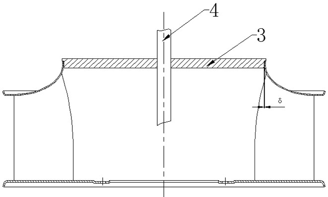
[0035] Such as figure 1 As shown, when the rear disk 11, blades 12, and front disk 13 of the centrifugal impeller are assembled and welded, the center of the front disk is positioned by the vertical mandrel 4 and the large disc 3, wherein the mandrel is the axial centerline of the impeller 1 , the gap between the large disk and the inner wall of the entrance of the front disk is δ, and the horizontal direction and the vertical direction of the front disk are all positioned. In the front disc of the prior art, the inner circle of the front disc has a certain degree of ellipticity due to uneven shrinkage and deformation during mold pressing. In order to ensure that the minimum inner diameter of the front disc can trap the large disc, the outer diameter of the large disc must be turned Small size, resulting in uneven distribution of mass in the circumf...

Embodiment 2

[0040] This embodiment specifically illustrates the function of the arc section of the main body.

[0041] Comparing Example 2 of the present invention with Comparative Prototype 1, except for the difference in the section arc of the arc section of the main body, the remaining parts of the ventilator are completely the same, and the matching motor and operating speed are also the same. The cross-sectional shape of the main body arc section of comparative prototype 1 is a circular arc, and the cross-sectional shape of the main body arc section of Example 2 is the curve of the main body arc section of the present invention, including a straight inlet section "ab", a main body arc section "bc", and a flat Straight exit section "cd" and exit flange section "def".

[0042] Embodiment 2 and comparative prototype 1 relevant dimensions are as follows:

[0043] D. 2 =526.6 mm

[0044] D. 0 =352.5 mm

[0045] D. 3 =566 mm

[0046] s=6mm

[0047] u=87 mm

[0048] v=53.5 mm

[0...

Embodiment 3

[0056] This embodiment specifically illustrates the function of the arc section of the main body through another impeller size.

[0057] Comparing Example 3 of the present invention with Comparative Prototype 2, except for the difference in the section arc of the arc section of the main body, the remaining parts of the ventilator are identical, and the matching motor and operating speed are also the same. The cross-sectional shape of the arc section of the main body of the comparative prototype 2 is a circular arc, and the arc section of the main body in Example 3 is the curve of the arc section of the main body of the present invention.

[0058] Embodiment 3 and comparative prototype 2 relevant dimensions are as follows:

[0059] D. 2 =639.6mm

[0060] D. 0 =444mm

[0061] D. 3 =716mm

[0062] s=7mm

[0063] u=97.8mm

[0064] v=68mm

[0065] θ=34.8°

[0066] v / u=0.695

[0067] The performance curve comparison of embodiment 3 and comparative prototype 2 sees Figur...


PUM


Abstract

The invention relates to a centrifugal impeller. The centrifugal impeller comprises a front disc, a rear disc and a plurality of blades evenly clamped between the front disc and the rear disc; the space defined by the adjacent blades, the front disc and the rear disc is an airflow channel in the impeller, and airflow axially enters the impeller from the front disc, passes through flow channels between the blades and then flows out from the periphery of the impeller; the front disc sequentially comprises a straight inlet section, a main body arc-shaped section, a straight outlet section and anoutlet flanging section from an airflow inlet to an airflow outlet; the straight inlet section is in a straight cylinder shape, the straight outlet section is in a circular ring shape, and an inlet end of the main body arc-shaped section is tangentially connected with the straight inlet section; and an outlet end of the main body arc-shaped section is tangentially connected with the straight outlet section.

Description

technical field [0001] The invention relates to the technical field of ventilators, in particular to a centrifugal impeller, and also relates to a ventilator comprising the centrifugal impeller. Background technique [0002] The centrifugal impeller mainly includes a rear disc, a front disc and some blades arranged therebetween, wherein the inner hole of the front disc is the impeller inlet. The basic forms of the front disc are straight front disc, conical front disc and arc front disc. The cross-sectional shape of the front disc has a great influence on the flow state in the blade flow channel, which in turn has a significant impact on the performance of the fan. The impeller with high efficiency usually adopts an arc-shaped front disc (usually a circular arc). Generally speaking, the radius r of the inner front end of the front disc should be as large as possible in order to weaken the separation and loss of the impeller inlet airflow when it turns. However, expanding t...

Claims


Application Information

Patent Timeline
IPC IPC(8): F04D29/30F04D29/28F04D25/08F04D17/16F04D29/62
CPCF04D25/08F04D17/16F04D29/30F04D29/28F04D29/626
Inventor 裘霖富徐天赐张职锋马杰凯俞晓骏刘伟
Owner 浙江科贸智能机电股份有限公司
Why Eureka
Try Eureka