Laser machine control method and system

A control method and control system technology, applied in the field of mechanical engineering control, can solve the problems of single human-computer interaction means, difficult trajectory planning, teaching programming, etc. Effect

Inactive Publication Date: 2021-01-22
GUANGZHOU INST OF RAILWAY TECH
View PDF9 Cites 0 Cited by
  • Summary
  • Abstract
  • Description
  • Claims
  • Application Information

AI Technical Summary

Problems solved by technology

However, with the improvement of production and manufacturing process requirements in mechanical engineering, the operation of industrial lasers in production and manufacturing is becoming more and more complicated, and higher requirements are put forward for the ope

Method used


Image

  • Laser machine control method and system
  • Laser machine control method and system
  • Laser machine control method and system

Examples


Embodiment 1

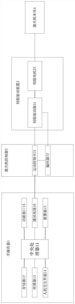
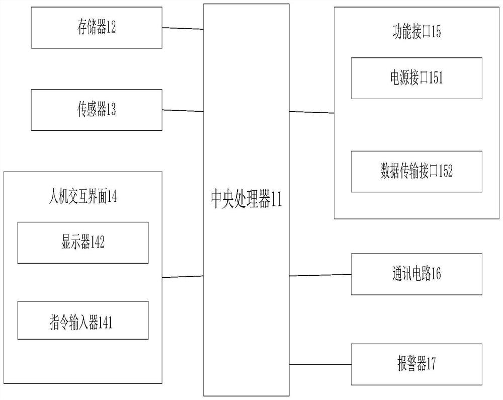
[0072] Example 1, such as figure 2 and image 3 As shown, the hand operator 1 includes a central processing unit 11, a memory 12, a sensor 13, a human-computer interaction interface 14, a functional interface 15 and a communication circuit 16; , the functional interface 15 is electrically connected with the communication circuit 16, and the communication circuit 16 is communicatively connected with the laser machine controller 2. Through the functional interface 15, necessary functions can be provided for the work of the hand manipulator 1; through the central processing unit 11, human The machine-machine interaction interface 14, the sensor 13 and the function interface 15 can provide a rich man-machine interaction platform for the manipulator operator, provide rich interactive means to complete the parameter setting and motion track planning of the laser machine body 4, improve the interaction effect, and then To realize the motion control and operation functions of the la...

Embodiment 2

[0073] Example 2, such as image 3As shown, the human-computer interaction interface 14 includes an instruction input device 141 and a display 142, and the central processing unit 11 is electrically connected to the instruction input device 141 and the display 142 respectively. The instruction input device 141 includes a three-dimensional mouse and a microphone, and also includes buttons and / or a touch screen The three-dimensional mouse and the microphone are all electrically connected to the central processing unit 11 respectively; the buttons are electrically connected to the central processing unit 11, and / or the touch screen is electrically connected to the central processing unit 11, and the three-dimensional mouse is combined with the buttons and / or the touch screen to facilitate The operator performs motion trajectory planning, such as completing the simulation of the laser machine body 4 and the virtual 3D working scene, completing the kinematic modeling of the laser ma...

Embodiment 3

[0074] Embodiment 3, the hand operator 1 also includes an alarm 17; the alarm 17 is electrically connected to the central processing unit 11, through the alarm 17, when a fault occurs during parameter setting and motion trajectory planning, an alarm signal can be sent in time To remind the operator to take corresponding solutions in time to ensure the smooth operation of the entire laser machine and avoid unnecessary losses.


PUM


Abstract

The invention relates to the field of mechanical engineering control, in particular to a laser machine control method and system. The method comprises the steps that 1, a manual operator carries out the data setting of a laser machine body, and transmits the set data to a laser machine controller; 2, the laser machine controller controls a servo driving device according to the set data; and 3, theservo driving device controls the laser machine body to operate according to the set data. By means of the method, rich man-machine interaction means can be provided, complex track planning can be rapidly completed, teaching programming does not need to be conducted in advance, the application range is wider, and the method can be widely popularized.

Description

technical field [0001] The invention relates to the field of mechanical engineering control, in particular to a laser machine control method and system. Background technique [0002] With the development of laser technology, industrial lasers are more and more widely used in the field of mechanical engineering technology. However, with the improvement of production and manufacturing process requirements in mechanical engineering, the operation of industrial lasers in production and manufacturing is becoming more and more complicated, and higher requirements are put forward for the operation methods of industrial lasers. The traditional laser machine operation method is human-computer interaction. The method is single, it is difficult to complete complex trajectory planning, and it needs to teach programming in advance, which has great limitations. Contents of the invention [0003] The technical problem to be solved by the present invention is to provide a laser machine c...

Claims


Application Information

Patent Timeline
IPC IPC(8): G05B19/414
CPCG05B19/414G05B2219/31137
Inventor 程智勇李晓娟陈文尉
Owner GUANGZHOU INST OF RAILWAY TECH
Why Eureka
Try Eureka