Supercharge Your Innovation With Domain-Expert AI Agents!

Three-dimensional design method for lap joint of front big foot bent part of hydraulic support base

A three-dimensional design, hydraulic support technology, applied in design optimization/simulation, computer-aided design, calculation, etc., can solve problems such as the inability to guarantee quality and the inaccurate size of the hydraulic support base, reduce the scrap rate of sheet materials, and achieve a reasonable design size. accurate effect

Active Publication Date: 2021-01-22
山西平阳煤机装备有限责任公司
View PDF9 Cites 0 Cited by
  • Summary
  • Abstract
  • Description
  • Claims
  • Application Information

AI Technical Summary

Problems solved by technology

[0005] The present invention overcomes the deficiencies in the prior art, and proposes a three-dimensional design method for the overlapping of the front big foot bending parts of the hydraulic support base; it solves the problem that the traditional design method cannot be used to design the hydraulic support base at present, and the quality cannot be guaranteed during on-site welding. The problem

Method used


Image

  • Three-dimensional design method for lap joint of front big foot bent part of hydraulic support base
  • Three-dimensional design method for lap joint of front big foot bent part of hydraulic support base
  • Three-dimensional design method for lap joint of front big foot bent part of hydraulic support base

Examples


Embodiment Construction

[0034] In order to make the technical problems, technical solutions and beneficial effects to be solved by the present invention clearer, the present invention will be further described in detail in combination with the embodiments and accompanying drawings. It should be understood that the specific embodiments described here are only used to explain the present invention, not to limit the present invention. The technical solutions of the present invention will be described in detail below in conjunction with the embodiments and accompanying drawings, but the scope of protection is not limited thereto.

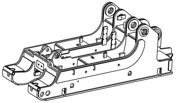
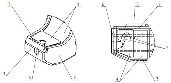
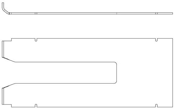
[0035] like figure 1 As shown in -4, the present invention provides a kind of three-dimensional design method of the big foot bending part lap before the hydraulic support base, utilizes the three-dimensional design software to create the geometric entity of the workpiece, and builds the simulation model of the big foot before the base, by folding it The interference and gap ...


PUM


Abstract

The invention relates to a three-dimensional design method for lap joint of a front big foot bent part of a hydraulic support base and belongs to the technical field of design of fully mechanized coalmining supporting equipment; problems that when a hydraulic support base is designed through a traditional design method at present, the size cannot be accurate, and the quality cannot be guaranteedduring on-site welding are solved. The base front big foot structure comprises an outer main rib, an inner main rib, a bottom plate, a cover plate, an inner reinforcing rib and round steel, the innermain rib is a single-bending plate, and the bottom plate is a double-bending plate; the method comprises the following steps of creating a geometric entity of a workpiece by utilizing three-dimensional design software, constructing a simulation model of a front big foot of a base, determining the correctness of a design size through interference and gap verification of a lap joint part of a bent part of the base, and outputting a flattening geometric model of the bent part after simulation is finished. The method is advantaged in that the design size given by the three-dimensional design method has logicality and is reasonable and accurate, the stress of the designed support better conforms to the reality, the tedious process is reduced, materials are saved, and meanwhile reference is provided for design of other supports of the same type.

Description

technical field [0001] The invention belongs to the technical field of coal mining support equipment design, and in particular relates to a three-dimensional design method for the lap joint of the big foot bending parts in front of a hydraulic support base. Background technique [0002] In the design of the existing hydraulic support base, the single-bending design of the inner main rib and the double-bending design of the bottom plate are particularly common. It is difficult to find a reasonable design method. [0003] In the traditional design method, the designer usually roughly gives the design size based on processing experience, or reserves a surplus size, and compares, manually trims, and fills with solder stacks after bending the two boards on site during a spot assembly in the workshop. Mainly, the cutting surface of the product after trimming is uneven and extremely unsightly. [0004] The design of this commonly used bracket not only has drawing problems such as...

Claims


Application Information

Patent Timeline
IPC IPC(8): G06F30/17G06F30/20G06T17/00G06F119/18
CPCG06F30/17G06F30/20G06T17/00G06F2119/18
Inventor 杨玥苏红娟白旭东杨忠宇李璟吴瑞杰霍玉婷
Owner 山西平阳煤机装备有限责任公司
Features
  • R&D
  • Intellectual Property
  • Life Sciences
  • Materials
  • Tech Scout
  • Unparalleled Data Quality
  • Higher Quality Content
  • 60% Fewer Hallucinations
Learn More