
A Wide Beam Dielectric Resonator Antenna

A dielectric resonator, wide beam technology, applied in resonant antennas, antennas, antenna parts and other directions, can solve problems such as narrow beams, and achieve the effect of increasing the resonance frequency, increasing the beam width, and broadening the bandwidth

Active Publication Date: 2021-07-27
XIDIAN UNIV
View PDF13 Cites 0 Cited by
  • Summary
  • Abstract
  • Description
  • Claims
  • Application Information

AI Technical Summary

Problems solved by technology

[0006] The purpose of the present invention is to propose a wide-beam dielectric resonator antenna for the above-mentioned defects in the prior art, which is used to solve the technical problem of the narrow beam existing in the prior art, so as to expand the application range of the antenna

Method used

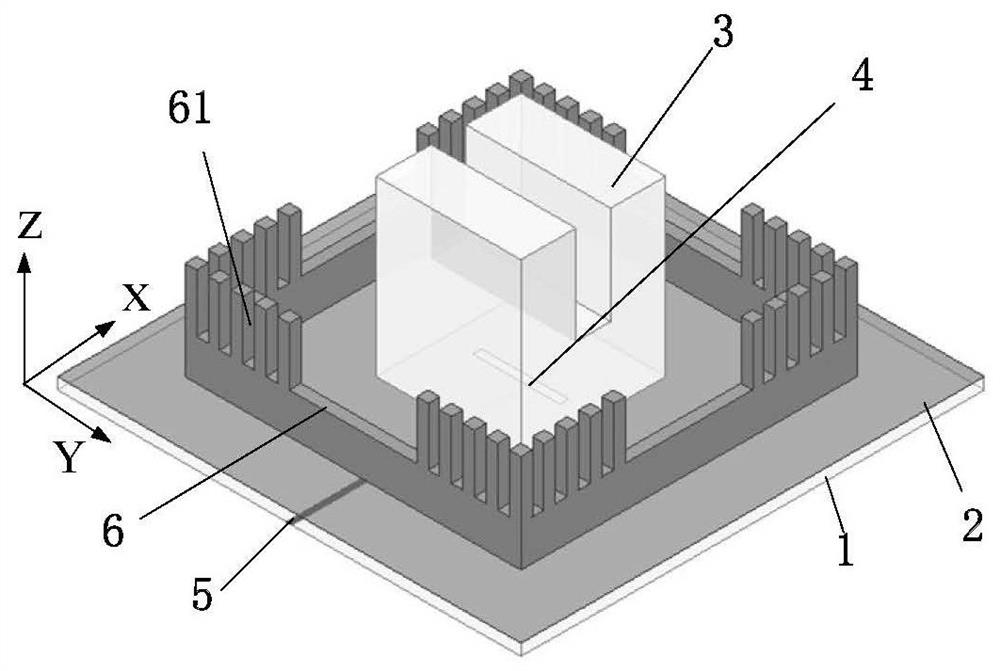
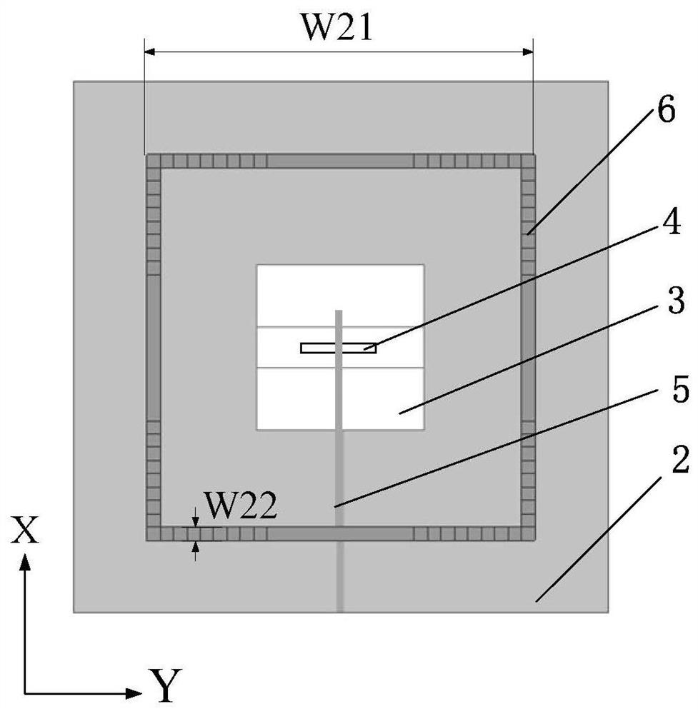
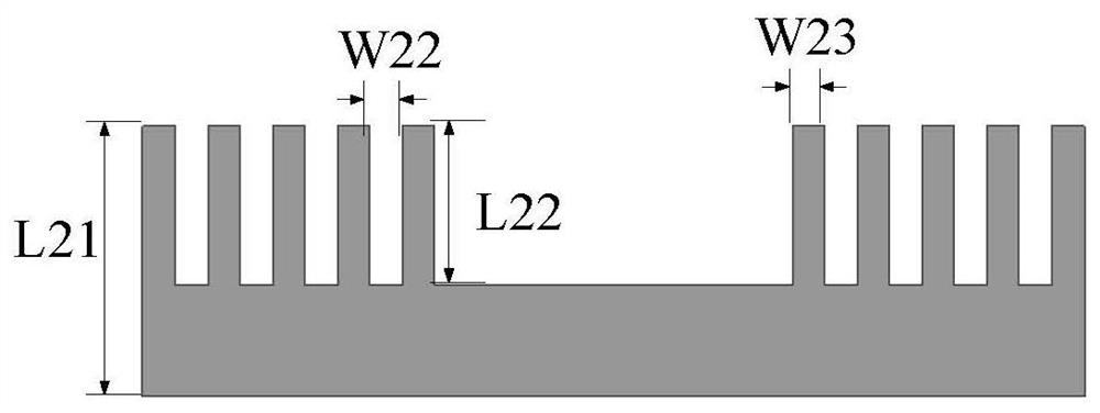

Image

  • A Wide Beam Dielectric Resonator Antenna
  • A Wide Beam Dielectric Resonator Antenna
  • A Wide Beam Dielectric Resonator Antenna

Examples


Embodiment Construction

[0023] The present invention will be further described in detail below in conjunction with the accompanying drawings and specific embodiments.

[0024] refer to figure 1 , the present invention includes: a dielectric substrate 1, a metal floor 2, a dielectric resonator 3, a rectangular coupling gap 4, a rectangular microstrip line 5 and a square annular metal wall 6, wherein:

[0025] The dielectric substrate 1 is a square FR4 dielectric board with a dielectric constant of 4.4, a side length of 80 mm, and a thickness of 0.8 mm.

[0026] The metal floor 2 is printed on the upper surface of the dielectric substrate 1 and has the same size as the dielectric substrate 1 . A rectangular coupling slit 4 is etched at the center of the metal floor 2 and parallel to the Y-axis. The size of the rectangular coupling slit 4 is 15mm×1.5mm.

[0027] The dielectric resonator 3 is fixed at the center of the upper surface of the dielectric substrate 1 . Since the working mode of the quadran...


PUM


Abstract

The invention proposes a wide-beam dielectric resonator antenna, which is used to solve the technical problem of narrow beam existing in the prior art, including a dielectric substrate, a metal floor printed on the upper surface of the dielectric substrate, and a metal floor fixed on the upper surface of the dielectric substrate. The cylindrical dielectric resonator at the center, the microstrip line printed on the lower surface of the metal floor and the square ring metal wall around the dielectric resonator; the center of the metal floor is provided with a rectangular coupling gap parallel to the Y axis; the dielectric resonator The top of the dielectric resonator is provided with a groove that passes through the central axis of the dielectric resonator and is parallel to the Y axis; the upper part of each side of the square annular metal wall is provided with a plurality of rectangular sawtooth; the rectangular microstrip line and the rectangular coupling slot are vertical in space intersection, and the intersection point, and the midpoint of the square annular metal wall are located on the central normal of the dielectric substrate, and the central axis of the dielectric resonator coincides with the central normal of the dielectric substrate. Wide beam with wide bandwidth.

Description

technical field [0001] The invention belongs to the technical field of antennas, and relates to a wide-beam dielectric resonator antenna, which can be applied to wireless communication systems such as mobile satellite communication and satellite positioning. Background technique [0002] With the rapid development of wireless communication, many wireless communication systems put forward higher requirements on the signal coverage of the antenna, and require the antenna to provide a larger signal coverage. Therefore, wide-beam antennas have received more and more attention and attention. [0003] The dielectric resonator antenna is a resonant cavity antenna. Since it was first proposed in 1983, the research on the dielectric resonator antenna has gained widespread attention. Compared with traditional antennas, dielectric resonator antennas have the advantages of higher design freedom, higher radiation efficiency, various feeding forms, and various antenna modes. However, th...

Claims


Application Information

Patent Timeline
Patent Type & Authority Patents(China)
IPC IPC(8): H01Q9/04H01Q1/36H01Q1/24H01Q25/04
CPCH01Q1/241H01Q1/36H01Q9/0485H01Q25/04
Inventor 焦永昌李睿洋王海燕张依轩
Owner XIDIAN UNIV
Learn More