Cooling and ventilating equipment for box-type transformer substation, and using method thereof

A box-type substation, cooling and ventilation technology, applied in the field of substations, can solve problems such as equipment damage, high temperature in substations, and inability to achieve gas filtration

Active Publication Date: 2021-01-22
山东德普电力有限公司
View PDF5 Cites 2 Cited by
  • Summary
  • Abstract
  • Description
  • Claims
  • Application Information

AI Technical Summary

Problems solved by technology

[0003] At present, during the use of substations, ventilation and heat dissipation equipment is indispensable, but the current ventilation and heat dissipation equipment still has the following deficiencies: 1. The gas flowing into the substation belongs to normal temperature gas, and the cooling effect is poor; 2. The gas cannot be cooled. Filtration makes the humidity of the gas entering the substation relatively high, and long-term

Method used


Image

  • Cooling and ventilating equipment for box-type transformer substation, and using method thereof
  • Cooling and ventilating equipment for box-type transformer substation, and using method thereof
  • Cooling and ventilating equipment for box-type transformer substation, and using method thereof

Examples


Embodiment 1

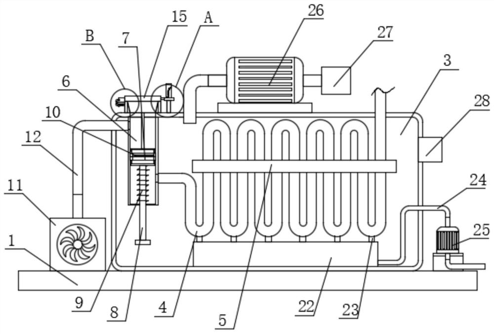
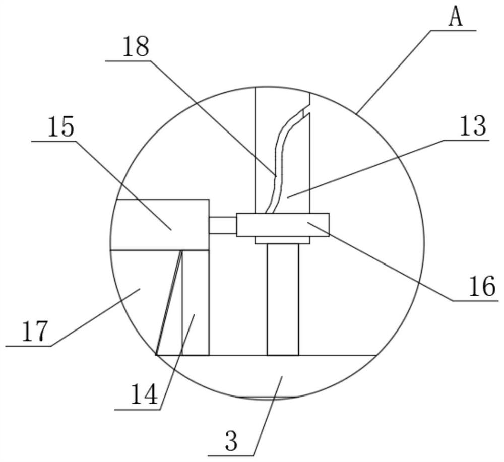
[0049] Embodiment one: if Figure 1-10As shown, a cooling ventilation device for a box-type substation includes a base 1, and the top of the base 1 is respectively fixed with a substation box 2 and a cooling box 3, and the cooling box 3 is located on one side of the substation box 2, cooling The dust removal assembly is fixedly installed on the inner wall of the top side of the box 3, and the top of the base 1 is fixedly installed with a turbo fan 11 on one side of the cooling box 3, and an air delivery pipe 12 is fixedly installed on the outlet end of the turbo fan 11, and the air delivery pipe One end of 12 extends into the cooling box 3 and communicates with the dust removal assembly. A fixed plate 5 is fixedly installed in the cooling box 3, and a plurality of heat exchange tubes 4 are fixedly installed on the fixed plate 5 at equal intervals. A plurality of heat exchange tubes 4 One end of each is connected with the dust removal assembly, and the bottom inner wall of the ...

Embodiment 2

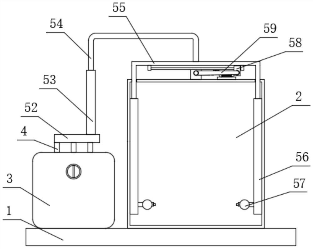
[0065] Embodiment two: if Figure 11-15 As shown, a cooling ventilation device for a box-type substation. The difference between this embodiment and Embodiment 1 is that the power assembly includes a drive motor 66 fixedly installed on the top of the substation box 2 and slidingly connected to the top of the substation box 2. The mobile frame 60, one side of the mobile frame 60 is fixedly equipped with a transmission ring 67, and the output shaft of the drive motor 66 is fixedly equipped with a transmission roller 64, the transmission roller 64 runs through the transmission ring 67, and the transmission roller 64 is provided with a transmission port 65 , and one side of the inner wall of the transmission ring 67 is fixed with a stop shaft 68, one end of the stop shaft 68 extends into the transmission port 65 and is connected with the inner wall of the transmission port 65, and the top of the substation box 2 is connected with a connecting shaft 62 for rotation. , and one end o...


PUM


Abstract

The invention discloses an application method of cooling and ventilation equipment for a box-type transformer substation. The equipment comprises a base, wherein the top of the base is fixedly provided with a transformer substation box body and a cooling box, the cooling box is located at one side of the transformer substation box body, the inner wall of one side of the top of the cooling box is fixedly provided with a dust removal assembly, a turbofan located on one side of the cooling box is fixedly installed at the top of the base, an air conveying pipe is fixedly installed at the air outlet end of the turbofan, one end of the air conveying pipe extends into the cooling box and communicates with the dust removal assembly, and a fixing plate is fixedly installed in the cooling box. According to the invention, gas entering a transformer substation can be cooled and dried, and uniform gas spraying can be realized after the gas is conveyed into the transformer substation box, so that the transformer substation box can be uniformly and quickly cooled, the temperature in the transformer substation box can be prevented from being too high, and the transformer substation box has good practicability.

Description

technical field [0001] The invention relates to the technical field of substations, in particular to a cooling ventilation device for a box-type substation and a usage method thereof. Background technique [0002] Box-type substation, also known as prefabricated substation or prefabricated substation. It is a kind of high-voltage switchgear, distribution transformer and low-voltage power distribution device. It is a factory prefabricated indoor and outdoor compact power distribution device arranged according to a certain wiring scheme, which is to organically combine functions such as transformer step-down and low-voltage power distribution. Together, they are installed in a moisture-proof, rust-proof, dust-proof, rodent-proof, fire-proof, theft-proof, heat-insulated, fully enclosed, and movable steel structure box, which is especially suitable for urban network construction and transformation. A brand new substation. The box-type substation is suitable for mines, factorie...

Claims


Application Information

Patent Timeline
IPC IPC(8): H02B1/56H02B1/46H02B1/28H02B1/54
CPCH02B1/565H02B1/46H02B1/28H02B1/54
Inventor 毛成成
Owner 山东德普电力有限公司
Why Eureka
Try Eureka