
Wireless charger coil provided with automatic winding production processing equipment

A technology for wireless chargers and processing equipment, applied in the manufacture of inductors, coils, inductors/transformers/magnets, etc., can solve problems such as reduced efficiency and time consumption, and achieve the effect of avoiding jams and facilitating work efficiency

Inactive Publication Date: 2021-01-22
深圳市辉迪机电科技有限公司
View PDF0 Cites 4 Cited by
  • Summary
  • Abstract
  • Description
  • Claims
  • Application Information

AI Technical Summary

Problems solved by technology

[0004] Aiming at the deficiencies of the existing technology, the present invention provides a wireless charger coil with automatic winding production and processing equipment, which solves the problem in the above background technology that after the coil of the internal part of the wireless charger is wound into a circle, it needs to pass through the adhesive tape Wrapping and wrapping the joints of the two sections of the coil to fix them, instead of manual operation in most symbiosis processes, it is necessary to fix the line segments in the fixture first, and then push the coil and adhesive tape through the fixture to fix it, thus reducing the efficiency through manual operation , and in the process of installing the coil on the fixture, it is also time-consuming to install due to the structure of the fixture

Method used

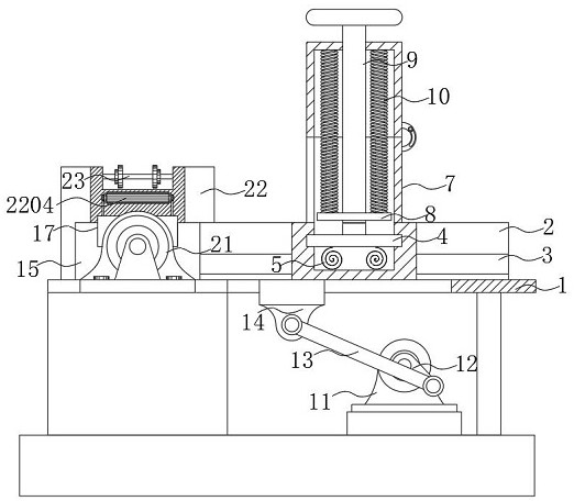
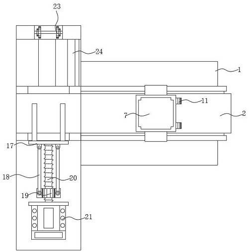
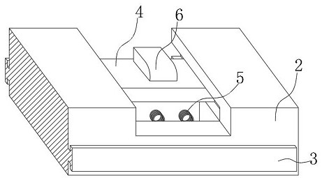

Image

  • Wireless charger coil provided with automatic winding production processing equipment
  • Wireless charger coil provided with automatic winding production processing equipment
  • Wireless charger coil provided with automatic winding production processing equipment

Examples


Embodiment Construction

[0028] The following will clearly and completely describe the technical solutions in the embodiments of the present invention with reference to the accompanying drawings in the embodiments of the present invention. Obviously, the described embodiments are only some, not all, embodiments of the present invention.

[0029] In the description of the present invention, unless otherwise stated, the meaning of "plurality" is two or more; the terms "upper", "lower", "left", "right", "inner", "outer" , "front end", "rear end", "head", "tail", etc. indicate the orientation or positional relationship based on the orientation or positional relationship shown in the drawings, and are only for the convenience of describing the present invention and simplifying the description, rather than Indicates or implies that the device or element referred to must have a particular orientation, be constructed and operate in a particular orientation, and therefore should not be construed as limiting the...


PUM


Abstract

The invention discloses a wireless charger coil provided with automatic winding production processing equipment. The wireless charger coil comprises a supporting frame, wherein a flow guide base is installed on the upper surface of the supporting frame, a control motor is installed at the bottom of the supporting frame, an operation table is arranged at the end of the left side of the supporting frame, an adhesive tape winding machine is arranged on the surface, opposite to a pressing and pushing plate, of the operation table, and a discharge port is formed below bottom of the finished surfaceof the adhesive tape winding machine. According to the invention, a clamping and pushing plate and a feeding bin are arranged on the left side and the upper surface of a flow guide base, and a coil bottom support is installed in the flow guide base, so that a coil in the feeding bin can be conveniently pushed into the clamping and pushing plate; and the clamping and pushing plate and the adhesivetape winding machine are oppositely arranged, so that the coil is conveniently pushed into the adhesive tape winding machine to be wrapped, the situation that one device is provided with one worker is avoided so as to reduce personnel operation and inconvenience during coil installation, and the working efficiency of coil wrapping is improved.

Description

technical field [0001] The invention relates to the technical field of wireless chargers, in particular to a wireless charger coil with automatic winding production and processing equipment. Background technique [0002] With the continuous improvement of requirements for power supply quality, safety, reliability, convenience, immediacy, special occasions, and special geographical environments for electrical equipment, the contact power transmission method is increasingly unable to meet actual needs. Wireless chargers It is a device that uses the principle of electromagnetic induction for charging. Its principle is similar to that of a transformer. By placing a coil at the sending and receiving ends, the coil at the sending end sends out an electromagnetic signal to the outside under the action of electricity, and the coil at the receiving end receives the electromagnetic signal and converts it to the outside world. Electromagnetic signals are converted into electric current...

Claims


Application Information

Patent Timeline
IPC IPC(8): H02J50/00H01F38/14H01F41/00H01F41/04H01F41/06H01F41/12
CPCH01F38/14H01F41/005H01F41/04H01F41/06H01F41/12H02J50/005
Inventor 张绍辉林锦萍李智鹏
Owner 深圳市辉迪机电科技有限公司
Learn More