Vehicle power supply

A power supply, power supply technology, applied in electrical components, vehicle components, circuits or fluid pipelines, etc., can solve the problems of difficult heat dissipation, power supply damage, power supply temperature rise, etc., to improve heat dissipation efficiency Effect

Active Publication Date: 2021-01-22
西安甘鑫科技股份有限公司
View PDF7 Cites 2 Cited by
  • Summary
  • Abstract
  • Description
  • Claims
  • Application Information

AI Technical Summary

Problems solved by technology

However, this makes it difficult for the heat generated inside the power supply to dissipate, and the heat accumulates in a small space, c

Method used


Image

  • Vehicle power supply
  • Vehicle power supply
  • Vehicle power supply

Examples


Embodiment 1

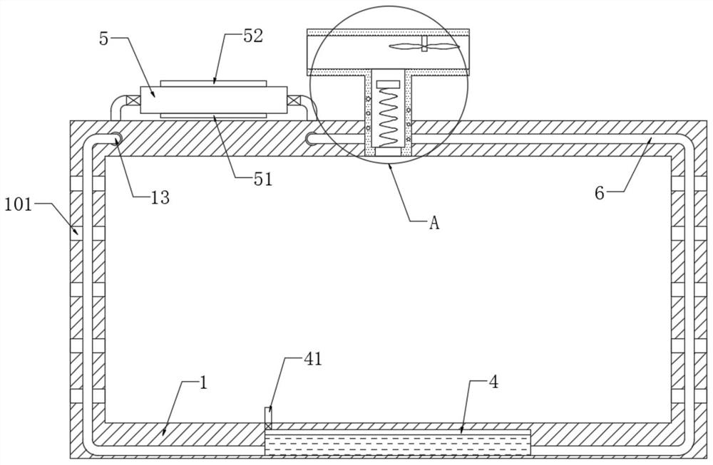
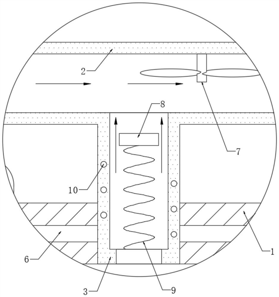
[0019] refer to Figure 1-2 , a vehicle power supply, comprising a supply housing 1, a power supply device is installed in the supply housing 1, the side wall of the supply housing 1 is provided with cooling holes 101, and the supply housing 1 is fixedly connected with The exhaust pipe 3 communicating with the inside thereof, the side wall of the exhaust pipe 3 is fixedly connected with the windward pipe 2 communicating with the inside thereof.

[0020] A liquid storage tank 4 is opened on the inner wall of the supplier housing 1, and the liquid storage tank 4 is filled with cooling liquid. The inner top of the liquid storage tank 4 is provided with an air intake pipe 41. It should be noted that the air intake pipe 41 can make the cooling liquid When flowing into or out of the liquid storage tank 4, the air can be discharged from the liquid storage tank 4 or flow into the liquid storage tank 4 for replenishment, so that the cooling liquid can flow smoothly. In addition, the ai...

Embodiment 2

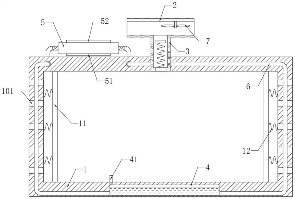
[0025] refer to image 3 , different from Embodiment 1, the supplier housing 1 is embedded with a dust filter 11, and the dust filter 11 is elastically connected to the inner wall of the supplier housing 1 through the second spring 12, and the second spring 12 and the spiral The coil 10 is coupled.

[0026] Due to the dust raised by the vehicle during driving, the dust will inevitably enter the interior of the power supply and gradually accumulate on the various electronic components in the power supply device, resulting in a decrease in the heat dissipation efficiency of the power supply. Therefore, this implementation can effectively prevent dust from falling on the power supply equipment in the supplier housing 1 by setting the dust filter 11, and at the same time, the induced current generated intermittently in the helical coil 10 is also constantly leading to the second spring 12, and the second spring 12 It shrinks when the power is turned on, and stretches and recovers...


PUM


Abstract

The invention discloses a vehicle power supply which comprises a supply shell. Power supply equipment is installed in the supply shell, heat dissipation holes are formed in the side wall of the supplyshell, an exhaust pipe communicated with the interior of the supply shell is fixedly connected to the supply shell, and a windward pipe communicated with the interior of the exhaust pipe is fixedly connected to the side wall of the exhaust pipe. A liquid storage tank is formed in the inner wall of the supply shell, an air inlet pipe is arranged at the inner top of the liquid storage tank, a liquid pumping barrel is fixedly connected to the upper end of the supply shell, and an electromagnet and an iron sheet are fixedly connected to the two opposite side walls of the liquid pumping barrel respectively. By arranging the windward pipe, the exhaust pipe and other components, the windward pipe extends out of a vehicle during installation, and when the vehicle runs, air flows in the windward pipe at a high speed, so that the air flow rate in the windward pipe is high, the air flow rate in the exhaust pipe is low, and hot air in the power supply can be brought out, and high temperature caused by heat accumulation in the power supply is prevented.

Description

technical field [0001] The invention relates to the technical field of power supplies, in particular to a vehicle power supply. Background technique [0002] In order to meet the use of various electrical equipment inside the vehicle, a power supply is often installed in the vehicle. However, the power supply for the vehicle is generally fixed in a relatively closed space in the vehicle to prevent the power supply from being damaged while the vehicle is running. collision. However, this makes it difficult to dissipate the heat generated inside the power supply, and the heat accumulates in a small space, causing the temperature of the power supply to rise rapidly, and the continuous high temperature can easily cause damage to the power supply. Accordingly, this application document proposes a vehicle power supply. Contents of the invention [0003] The object of the present invention is to propose a vehicle power supply to solve the shortcomings in the prior art. [0004...

Claims


Application Information

Patent Timeline
IPC IPC(8): H05K7/20B01D46/10B60R16/03H02M1/00
CPCH02M1/00H05K7/20136H05K7/20145H05K7/20327B01D46/10B60R16/03
Inventor 郭四新
Owner 西安甘鑫科技股份有限公司
Why Eureka
Try Eureka