
A plywood plate cutting mechanism

A cutting mechanism, a technology for plywood, used in other plywood/plywood appliances, special forming/shaping machines, machine tools suitable for grinding the edges of workpieces, etc., which can solve problems such as warped flashes and easily cut workers.

Active Publication Date: 2021-07-06
临沂鲁地装饰材料有限公司
View PDF8 Cites 0 Cited by
  • Summary
  • Abstract
  • Description
  • Claims
  • Application Information

AI Technical Summary

Problems solved by technology

However, when cutting the plate, the edge is easy to produce raised flash, and the worker is easy to cut the worker when carrying it.

Method used


Image

  • A plywood plate cutting mechanism
  • A plywood plate cutting mechanism
  • A plywood plate cutting mechanism

Examples


Embodiment Construction

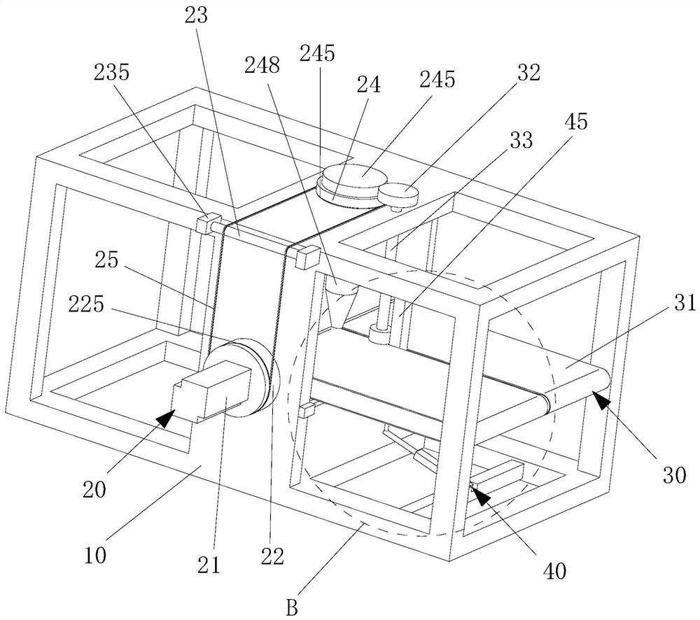
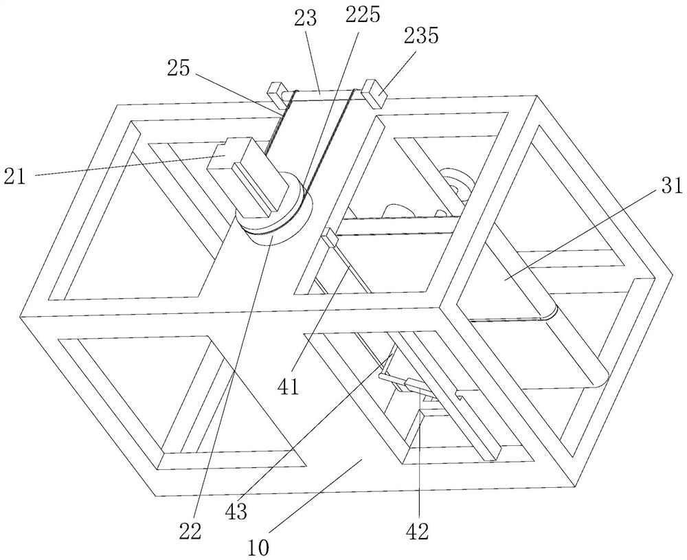
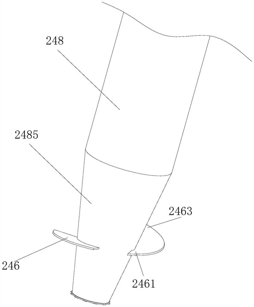
[0019] see Figure 1 to Figure 4 , a plate cutting mechanism for plywood, comprising a working frame 10, a driving assembly 20, a transmission assembly 30 and a cutting assembly 40, one end of the working frame 10 is rotatably provided with a driven roller 11, and the driving assembly 20 includes a driving motor 21, a driving roller , driving wheel 22, relay roller 23, driven wheel 24 and power strip 25, driving motor 21 is installed on the side wall of work frame 10, driving wheel 22 is installed on the output shaft of driving motor 21, and the opposite two ends of driving roller are respectively Rotately connected on the opposite side walls of the working frame 10, one end of the drive roller is also fixedly connected with the output shaft of the driving motor 21, the relay roller 23 is rotatably installed on the side wall top of the working frame 10, and the driven wheel 24 is rotatably installed On the top surface of the working frame 10, the power strip 25 is ring-shaped,...


PUM


Abstract

The invention relates to a plate cutting mechanism for plywood. The plate cutting mechanism for plywood includes a working frame, a driving assembly, a transmission assembly and a cutting assembly, one end of the working frame is rotatably provided with a driven roller, and the driving assembly includes a driving motor, a driving roller, a driving wheel, a relay roller, a driven wheel and The power thong, the driving motor is installed on the side wall of the working frame, the driving wheel is installed on the output shaft of the driving motor, the opposite ends of the driving roller are respectively connected to the opposite two walls of the working frame in a rotational manner, and one end of the driving roller is also It is fixedly connected with the output shaft of the drive motor, and the intermediate roller is rotatably installed on the top of the side wall of the working frame. When the plywood plate cutting mechanism cuts the plate, the edge of the plate is prone to produce raised flash. The invention uses the grinding disc to remove the flash by friction, improving the cutting quality and the safety performance of subsequent handling.

Description

technical field [0001] The invention relates to a plate cutting mechanism for plywood. Background technique [0002] Plywood includes decorative veneer veneer plywood, which can be divided into single-sided decorative veneer veneer plywood and double-sided decorative veneer veneer plywood according to the decorative surface; it can be divided into I decorative veneer veneer plywood, II Class III decorative veneer veneer plywood and Class III decorative veneer veneer plywood; according to the texture of the decorative veneer, it can be divided into radial decorative veneer veneer plywood and chord decorative veneer veneer plywood. In the production process of plywood, it is often necessary to cut a board into two pieces. However, the edge when cutting the plate is prone to warping flashes, and the workers are easy to cut the workers when they are carrying them. Contents of the invention [0003] Based on this, it is necessary to provide a plywood plate cutting mechanism t...

Claims


Application Information

Patent Timeline
Patent Type & Authority Patents(China)
IPC IPC(8): B27D5/00B27C5/00B24B9/18
CPCB24B9/18B27C5/00B27D5/00
Inventor 李军
Owner 临沂鲁地装饰材料有限公司
Learn More