Four-engine double-rotary-arm vertical take-off and landing unmanned aerial vehicle and flight control method thereof

A vertical take-off and landing, unmanned aerial vehicle technology, applied in vertical take-off and landing aircraft, unmanned aerial vehicles, aircraft control and other directions, can solve the problem of insufficient rotor control margin, reduced cruise speed and endurance, and increased overall aircraft resistance, etc. question

Active Publication Date: 2021-01-26
ARMY ENG UNIV OF PLA
View PDF6 Cites 8 Cited by
  • Summary
  • Abstract
  • Description
  • Claims
  • Application Information

AI Technical Summary

Problems solved by technology

But it also has obvious deficiencies: First, the four-rotor component does not work in level flight, which becomes dead weight, reduces the load capacity of the UAV, increases the resistance of the whole aircraft, and has a relatively large decrease in cruising speed and endurance time. The second is that the fixed-wing components do not work when hovering, so that the control of the UAV is completely dependent on the rotor, and the aerodynamic structures such as the main wing and tail are prone to generate large aerodynamic moments under external interference, which is prone to insufficient rotor control margin. question

Method used


Image

  • Four-engine double-rotary-arm vertical take-off and landing unmanned aerial vehicle and flight control method thereof
  • Four-engine double-rotary-arm vertical take-off and landing unmanned aerial vehicle and flight control method thereof
  • Four-engine double-rotary-arm vertical take-off and landing unmanned aerial vehicle and flight control method thereof

Examples


Embodiment Construction

[0048] In the following description, specific details such as specific system structures and technologies are presented for the purpose of illustration rather than limitation, so as to thoroughly understand the embodiments of the present invention. It will be apparent, however, to one skilled in the art that the invention may be practiced in other embodiments without these specific details. In other instances, detailed descriptions of well-known systems, devices, circuits, and methods are omitted so as not to obscure the description of the present invention with unnecessary detail.

[0049] In order to illustrate the technical solutions of the present invention, specific examples are used below to illustrate.

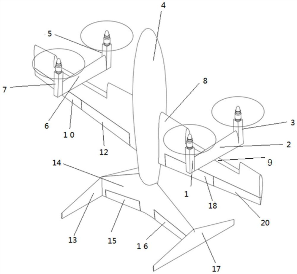
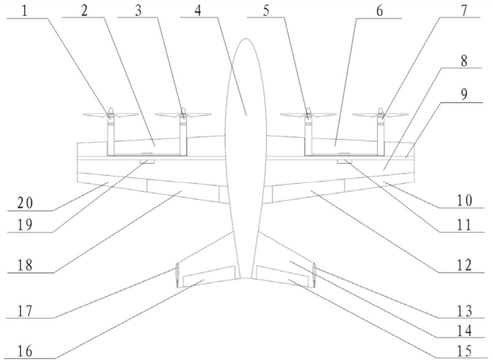
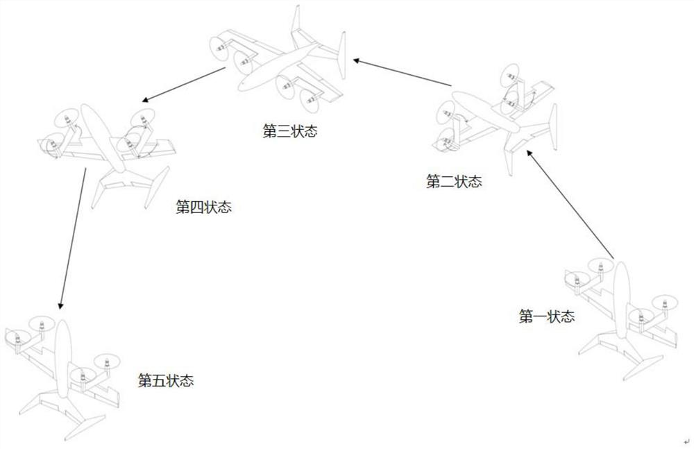
[0050] figure 1 , figure 2 A schematic diagram of a four-engine dual-arm vertical take-off and landing drone provided in an embodiment of the present invention is described in detail as follows. figure 1 When the UAV is in the vertical take-off and landing mode with...


PUM


Abstract

The invention is applicable to the technical field of unmanned aerial vehicle control, and provides a four-engine double-rotary-arm vertical take-off and landing unmanned aerial vehicle and a flight control method thereof. The four-engine double-rotary-arm vertical take-off and landing unmanned aerial vehicle comprises a left rotary arm arranged at the left front middle part of a main wing, is fixedly connected with a left rotary arm driving mechanism, forms a cross intersection structure together with the main wing and rotates 90 degrees in a flight process; a right rotary arm is arranged atthe right front middle part of the main wing, is fixedly connected with a right rotating arm driving mechanism, forms a cross intersection structure together with the main wing, and rotates by 90 degrees in the flying process; a first power assembly and a second power assembly are fixedly connected to the left end and the right end of the left rotary arm respectively, and a third power assembly and a fourth power assembly are fixedly connected to the left end and the right end of the right rotary arm respectively. The unmanned aerial vehicle can vertically take off and land, the requirement for a take-off or recovery site is lowered, the structure is simple and easy to control, the lift-drag ratio of the whole unmanned aerial vehicle can be increased through the four-engine double-spiral-arm structural design, and therefore the unmanned aerial vehicle is high in aerodynamic efficiency, long in cruising time and high in cruising speed.

Description

technical field [0001] The invention belongs to the technical field of unmanned aerial vehicle structure design and unmanned aerial vehicle control, and in particular relates to a four-engine double-rotary-arm vertical take-off and landing unmanned aerial vehicle and a flight control method thereof. Background technique [0002] Now drones are more and more widely used in aerial surveying and mapping, power inspection, express delivery, disaster prevention and mitigation, military reconnaissance and other fields. Among them, the widely used models include: fixed-wing drones, multi-axis rotor drones Human-machine and fixed-wing-four-rotor composite UAVs, but these types of UAVs are always facing some difficult contradictory problems while greatly improving the operating efficiency of the applied industries: [0003] Fixed-wing UAVs have mature technology, high aerodynamic efficiency, long battery life, fast cruising speed, and large operating area per sortie, but the traditio...

Claims


Application Information

Patent Timeline
Patent Type & Authority Applications(China)
IPC IPC(8): B64C27/26B64C39/02B64C29/00B64C19/00
CPCB64C27/26B64C39/02B64C29/00B64C19/00B64U10/25B64U2201/00B64U50/19
Inventor 邸彦佳陈自力高喜俊杨森李宝晨郝永锋党雪江苏立军林志龙
Owner ARMY ENG UNIV OF PLA
Why Eureka
Try Eureka