A sensor phase compensation device, method and magnetic levitation system

A phase compensation and sensor technology, applied in the field of magnetic suspension systems, can solve problems such as affecting the stability of shaft suspension

Active Publication Date: 2021-11-09
GREE ELECTRIC APPLIANCES INC
View PDF6 Cites 0 Cited by
  • Summary
  • Abstract
  • Description
  • Claims
  • Application Information

AI Technical Summary

Problems solved by technology

[0004] The purpose of the present invention is to provide a sensor phase compensation device, method and magnetic levitation system to solve the problem of inaccurate position signal of the detected rotating shaft when there is a phase difference between the two sensor sine wave signals in the control of the magnetic levitation bearing. The problem of affecting the suspension stability of the shaft is to achieve the effect of phase compensation for the phase difference of the sine wave signals of the two sensors to improve the accuracy of the detected position signal of the rotating shaft and thus improve the suspension stability of the shaft

Method used


Image

  • A sensor phase compensation device, method and magnetic levitation system
  • A sensor phase compensation device, method and magnetic levitation system
  • A sensor phase compensation device, method and magnetic levitation system

Examples


Embodiment Construction

[0039] In order to make the purpose, technical solution and advantages of the present invention clearer, the technical solution of the present invention will be clearly and completely described below in conjunction with specific embodiments of the present invention and corresponding drawings. Apparently, the described embodiments are only some of the embodiments of the present invention, but not all of them. Based on the embodiments of the present invention, all other embodiments obtained by persons of ordinary skill in the art without making creative efforts belong to the protection scope of the present invention.

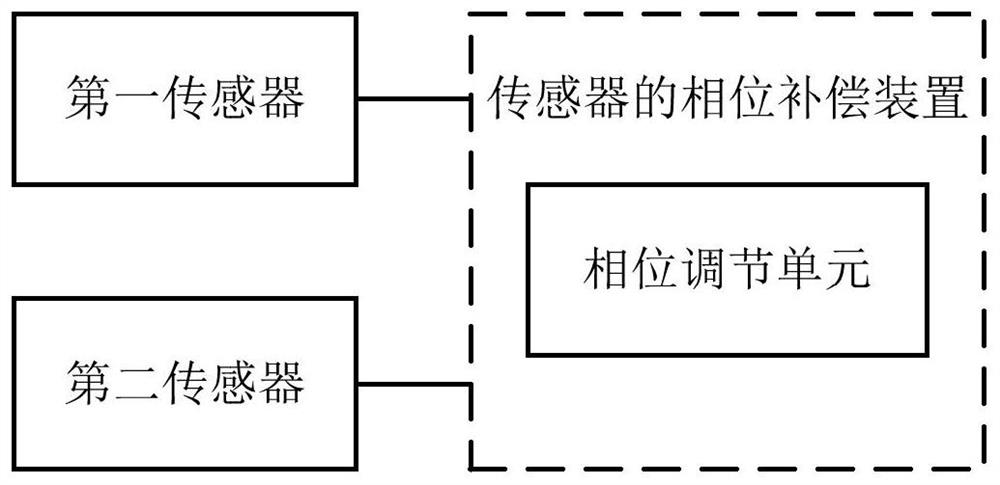
[0040] According to an embodiment of the present invention, a phase compensation device for a sensor is provided. see figure 1 A schematic structural view of an embodiment of the device of the present invention is shown. The phase compensation device of the sensor can be applied in the magnetic suspension bearing control of the magnetic suspension system. In the...


PUM


Abstract

The invention discloses a sensor phase compensation device, method and magnetic levitation system. In the device, a first sensor and a second sensor are located at a group of diagonal positions of a rotating shaft in the magnetic levitation system; the first sensor can output a first acquisition signal; a second sensor capable of outputting a second acquisition signal; a phase adjustment unit configured to determine the phase difference between the first acquisition signal and the second acquisition signal, and perform phase adjustment on the phase difference to Phase compensation is performed for the lead or lag of the phase difference, so that the phases of the first acquisition signal and the second acquisition signal are consistent. In this scheme, in the magnetic suspension bearing control, by compensating the phase difference of the sine wave signals of the two sensors, the accuracy of the detected position signal of the rotating shaft can be improved, thereby improving the suspension stability of the shaft.

Description

technical field [0001] The invention belongs to the technical field of magnetic levitation systems, and in particular relates to a phase compensation device, method and magnetic levitation system of a sensor, especially a phase compensation sensor (such as an eddy current sensor), in particular to a phase compensation circuit of an eddy current sensor, a magnetic levitation system and its The phase compensation method of the sensor. Background technique [0002] In the magnetic suspension bearing control, the voltage signal of the shaft displacement can be obtained by using the difference of the sine wave signal of two sensors. However, when there is a phase difference between the sine wave signals of the two sensors, the position signals of the rotating shaft detected by the two sensors are inaccurate, which affects the suspension stability of the central shaft controlled by the magnetic bearing. [0003] The above content is only used to assist in understanding the techni...

Claims


Application Information

Patent Timeline
Patent Type & Authority Patents(China)
IPC IPC(8): G01D5/244G05F1/56
CPCG01D5/244G05F1/561
Inventor 严安顺李旭明王凡朱振宇赵聪
Owner GREE ELECTRIC APPLIANCES INC
Why Eureka
Try Eureka