Eureka AIR delivers breakthrough ideas for toughest innovation challenges, trusted by R&D personnel around the world.

A charging ripple suppression circuit of an on-board charger and its control method

An on-board charger and ripple suppression technology, applied in battery circuit devices, efficient vehicle charging, electric vehicle charging technology, etc., can solve problems such as increasing product cost, reducing system bandwidth, and reducing product service life, and achieving extended use. longevity, improving product performance, and suppressing low-frequency ripple

Active Publication Date: 2022-08-02
ZHEJIANG GEELY HOLDING (GROUP) CO LTD +1
View PDF0 Cites 0 Cited by
  • Summary
  • Abstract
  • Description
  • Claims
  • Application Information

AI Technical Summary

Problems solved by technology

In view of the above two methods to solve the low-frequency ripple, the former, increasing the parallel capacitance of the busbar or adding an active filter device can effectively suppress the low-frequency ripple, but this measure needs to increase the product volume and increase the product cost. The use of capacitors will also reduce the service life of the product. In the latter solution, the introduction of a low-frequency ripple control loop will reduce the system bandwidth, affect the dynamic response speed of the system, and reduce the reliability of the system.

Method used


Image

  • A charging ripple suppression circuit of an on-board charger and its control method
  • A charging ripple suppression circuit of an on-board charger and its control method
  • A charging ripple suppression circuit of an on-board charger and its control method

Examples


Embodiment 1

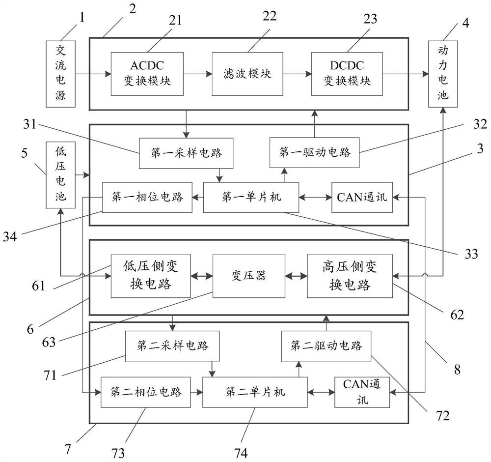
[0064] In the field of electric vehicles, the stability of the on-board charger has always been an important condition for the efficient output of electric vehicles, but when the charger is working, the DC bus output by the output circuit will have low-frequency ripples twice the power frequency, and the existence of low-frequency ripples may As a result, the battery management system (BMS) calculates the remaining power (SOC) inaccurately. In severe cases, it may cause overcharge, affecting battery life and safety. Therefore, in order to improve the working stability and high performance of the charger, the embodiments of this specification provide a charging ripple suppression circuit for an on-board charger, which can suppress the above-mentioned low-frequency ripple.

[0065] Specifically, as figure 1 As shown in the figure, a schematic diagram of the connection of a charging ripple suppression circuit of an on-board charger (OBC) provided by the embodiment of this specifi...


PUM


Abstract

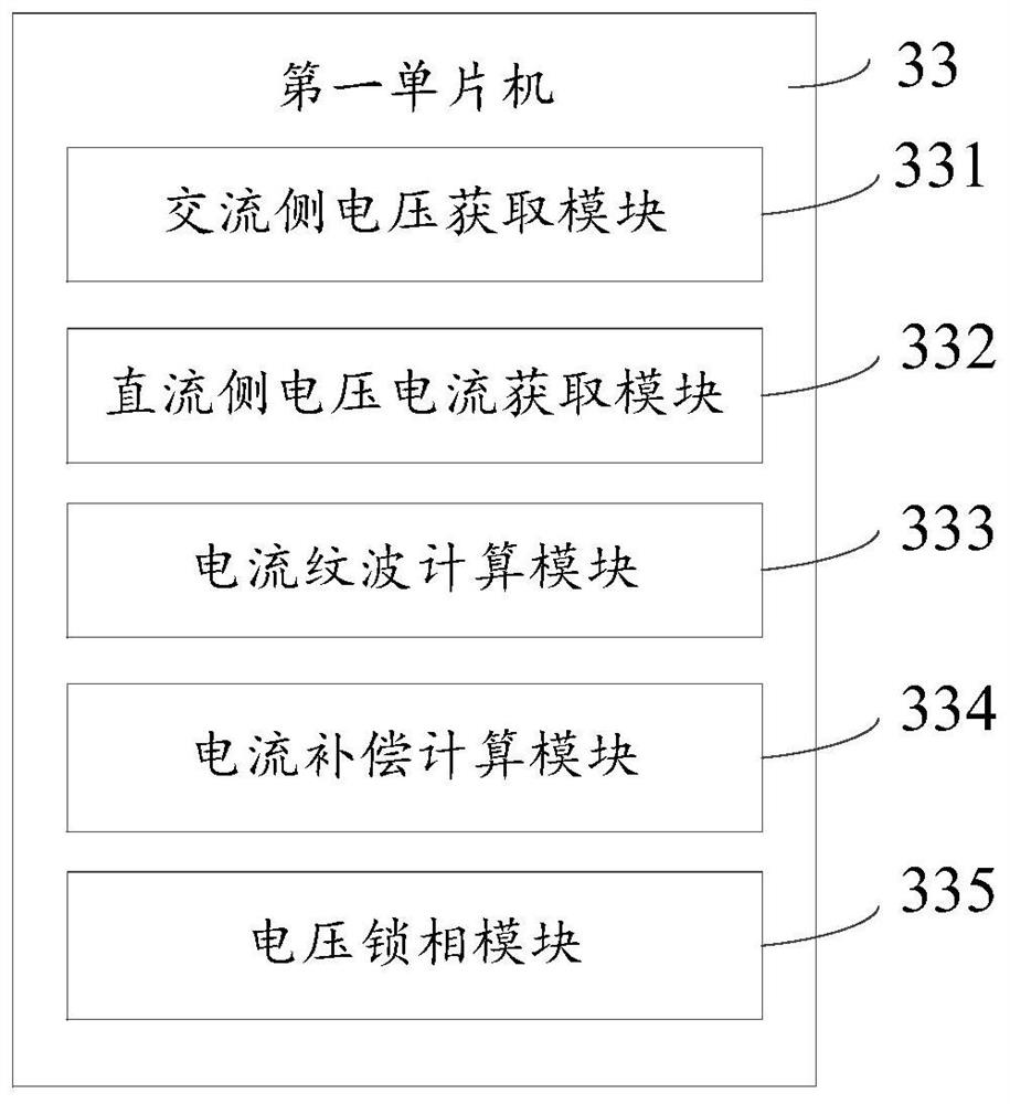
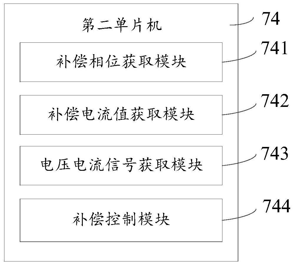
The invention discloses a charging ripple suppression circuit of a vehicle-mounted charger and a control method thereof. The suppression circuit comprises: an AC power supply is used to provide power to a main power circuit of the charger; the main power circuit of the charger is used to pass the AC power through The rectification is converted into DC power, and the converted DC power is charged to the power battery; the bidirectional conversion circuit is used to realize the bidirectional power conversion between the power battery and the low-voltage battery, so as to realize the ripple compensation at the output end of the main power circuit of the charger; A control circuit is used to control the operation of the main power circuit of the charger, the second control circuit is used to control the operation of the bidirectional conversion circuit; the communication circuit is used to realize the communication between the first control circuit and the second control circuit, without increasing the product cost. On the premise, the low-frequency ripple during single-phase operation is suppressed, and the cost of solving the ripple current problem is saved.

Description

technical field [0001] The invention relates to the technical field of chargers, in particular to a charging ripple suppression circuit of a vehicle-mounted charger and a control method thereof. Background technique [0002] At present, most of the on-board chargers are single-phase chargers with a power level of 3.3kW or 6.6kW. The topology circuit usually adopts the front stage PFC (power factor correction unit) and the rear stage LLC (a DC conversion topology). The power factor of the grid needs to be above 0.99, that is, the current is required to be in the same phase as the grid voltage. Affected by this, the DC bus output by the PFC (power factor correction unit) output circuit must have a low-frequency ripple twice the power frequency, which will eventually be reflected in the DC output of the power battery. The above problems will also occur when the three-phase on-board charger works in a phase loss or single-phase state. The ripple will have an impact on the work...

Claims


Application Information

Patent Timeline
Patent Type & Authority Patents(China)
IPC IPC(8): H02M1/14H02M3/24H02M7/04H02J7/02B60L53/20B60L53/22
CPCH02M1/143H02M3/24H02M7/04H02J7/02B60L53/20B60L53/22H02J2207/20B60L2210/30B60L2210/10Y02T10/92
Inventor 刘长江郭水保刘宇谢世滨
Owner ZHEJIANG GEELY HOLDING (GROUP) CO LTD
Why Eureka
Eureka Blog
Learn More