

Gynecological scalpel cleaning device
A cleaning device and scalpel technology, applied in surgery, medical science, diagnosis, etc., can solve the problems of time-consuming, labor-intensive, low-efficiency cleaning, and achieve the effect of high-efficiency cleaning, improving work efficiency and saving manpower
- Summary
- Abstract
- Description
- Claims
- Application Information
AI Technical Summary
Problems solved by technology
Method used
Image

Examples
Embodiment 1
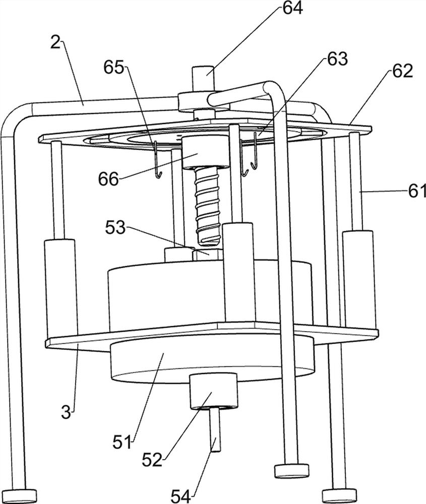
[0029] A gynecological scalpel cleaning device, such as figure 1 with figure 2 As shown, it includes a base plate 1, a bracket 2, a placement plate 3, a support plate 4, a cleaning component 5, and a lifting component 6. The top of the base plate 1 is connected to the bracket 2, and the middle of the top of the base plate 1 is connected to the placement plate 3. The left side of the top of the base plate 1 A support plate 4 is connected, a cleaning assembly 5 is connected to the center of the placing plate 3 in a rotating manner, and a lifting assembly 6 is slidingly connected to the top of the placing plate 3 .
[0030] The cleaning assembly 5 includes a cleaning frame 51, a rotating rod 52, a rhombus rod 53 and a first rotating shaft 54. The middle part of the placement plate 3 is rotatably connected with the cleaning frame 51, and the center position of the cleaning frame 51 is rotatably connected with a rotating rod 52. A rhombus rod 53 is connected to the top of the rod...
Embodiment 2
[0034] On the basis of Example 1, such as image 3 As shown, the drive assembly 7 is also included, and the drive assembly 7 includes a motor 71, a missing gear 72, a second rotating shaft 73, a first gear 74, a first bevel gear 75, a third rotating shaft 76 and a second bevel gear 77. Plate 4 top rear side is equipped with motor 71, and motor 71 output shafts are connected with missing gear 72, and support plate 4 top front side is connected with second rotating shaft 73 in rotation, and second rotating shaft 73 rear side is connected with first gear 74, the first The gear 74 is meshed with the missing gear 72, the front side of the second rotating shaft 73 is connected with the first bevel gear 75, the left side of the top of the bottom plate 1 is connected with the third rotating shaft 76, and the middle part of the third rotating shaft 76 is connected with the second bevel gear 77, The second bevel gear 77 meshes with the first bevel gear 75 , and the third rotating shaft ...
Embodiment 3
[0037] On the basis of Example 2, such as image 3 As shown, a rotating assembly 8 is also included. The rotating assembly 8 includes a fourth rotating shaft 81, a second gear 82, a third bevel gear 83, a fifth rotating shaft 84 and a fourth bevel gear 85. The fourth rotating shaft 81 is connected, the second gear 82 is connected to the rear side of the fourth rotating shaft 81, the second gear 82 is meshed with the missing gear 72, the third bevel gear 83 is connected to the front side of the fourth rotating shaft 81, and the left front of the base plate 1 The upper side of the fifth rotating shaft 84 is connected with a fourth bevel gear 85 , the fourth bevel gear 85 is meshed with the third bevel gear 83 , and the fifth rotating shaft 84 is connected to the first rotating shaft 54 through transmission.
[0038]When the missing gear 72 is not meshed with the first gear 74, the missing gear 72 rotates to drive the second gear 82 to rotate, the second gear 82 rotates to driv...
PUM
 Abstract
Description
Claims
Application Information