Paint feeding machine for building wall surface spraying

A technology for walls and coatings, applied in mixers, mixer accessories, shaker/oscillation/vibration mixers, etc., can solve problems such as uneven distribution of media and easy agglomeration, and achieve the effect of ensuring the quality of spraying

Inactive Publication Date: 2021-01-29
侯晓松
View PDF4 Cites 6 Cited by
  • Summary
  • Abstract
  • Description
  • Claims
  • Application Information

AI Technical Summary

Problems solved by technology

[0005] The object of the present invention is to solve the problem of uneven distribution of medium and easy caking in the above-mentioned paint, and provide a paint feeder for building wall spraying with uniform components and not easy to agglomerate

Method used


Image

  • Paint feeding machine for building wall surface spraying
  • Paint feeding machine for building wall surface spraying
  • Paint feeding machine for building wall surface spraying

Examples


Embodiment 1

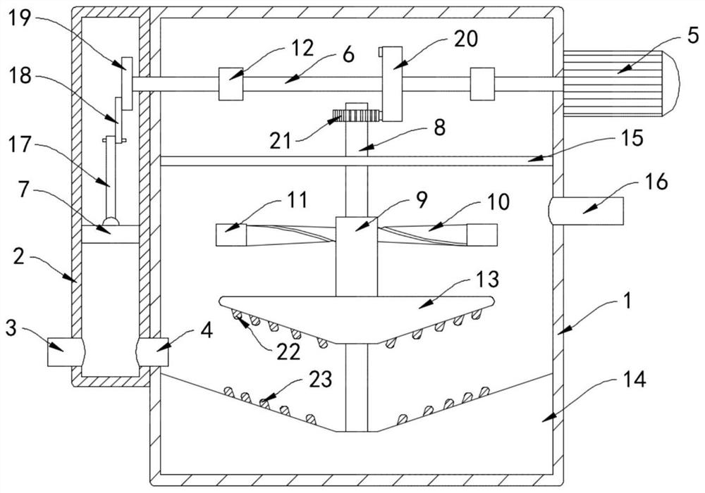
[0021] Such as Figure 1-2 As shown, a paint feeder for building wall surface spraying includes a housing 1, a feed box 2 is installed on the side wall of the housing 1, and a one-way feed pipe 3 is installed on the side wall of the feed box 2 , the one-way feed pipe 3 only allows the external paint to enter the feed box 2, and the feed box 2 communicates with the housing 1 through the one-way communication pipe 4, and the one-way communication pipe 4 only allows paint to enter the housing from the feed box 2 1, a horizontally arranged sealing plate 15 is installed in the housing 1, and the sealing plate 15 plays a role of sealing and isolating the paint. The evenly stirred paint in the inner and upper layers can be discharged into the sprayer through the discharge pipe 16 .

[0022] Drive motor 5 is installed on the side wall of housing 1, and drive motor 5 is a servo motor. During work, control drive motor 5 runs at a slower speed of 180r / min, and the output shaft of drive ...

Embodiment 2

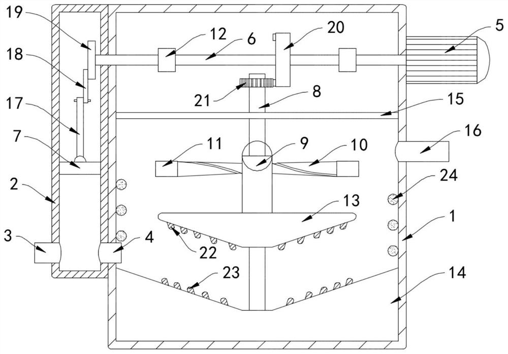
[0030] Such as image 3 As shown, the difference between this embodiment and Embodiment 1 is that an electromagnetic spring 24 is wound on the inner wall of the housing 1, and the head and tail ends of the electromagnetic spring 24 are electrically connected to form a closed loop, and the lower end of the electromagnetic spring 24 is connected to the grinding The upper surface of the groove 14 is fixedly connected.

[0031]In this embodiment, when the permanent magnet block 11 is subjected to the repulsive force of the ring magnet 12 and moves to a lower position close to the electromagnetic spring 24, as the stirring blade 10 drives the permanent magnet block 11 to rotate, the magnetic flux in the electromagnetic spring 24 changes, According to the principle of electromagnetic induction, when the magnetic flux in the closed loop changes, an induced current is generated in the closed loop, and then an induced current is generated in the electromagnetic spring 24, and an induce...


PUM


Abstract

The invention belongs to the field of building equipment, and particularly relates to a paint feeding machine for building wall surface spraying. The machine comprises a shell, a feeding box is installed on the side wall of the shell, a one-way feeding pipe is installed on the side wall of the feeding box, the feeding box is communicated with the shell through a one-way communicating pipe, and a driving motor is installed on the side wall of the shell. An output shaft of the driving motor extends into the shell and is coaxially provided with a rotating shaft, a piston block slides in the feeding box in a sealed mode, the piston block is connected with the rotating shaft through a feeding mechanism, a vertically-arranged rotating rod is arranged in the shell in a rotating mode, the rotatingshaft is connected with the rotating rod through a transmission mechanism, and a sleeve is connected to the exterior of the rotating rod in a sliding mode. A plurality of stirring blades are mountedon the side wall of the sleeve, and a permanent magnet block is mounted at one end of each stirring blade. The paint feeding machine can stir paint, promote flowing and uniform mixing of all components in the paint, guarantee the spraying effect, and grind and crush agglomerates deposited at the bottom of a grinding groove to guarantee the spraying quality.

Description

technical field [0001] The invention belongs to the field of construction equipment, in particular to a paint feeder for spraying paint on building walls. Background technique [0002] Most wall paints are made of synthetic resin emulsion as the base material, water as the dispersion medium, pigments, fillers and additives are added, and the paint is made through a certain process. Most of the existing building walls are sprayed wall paint (latex paint). Paint) to achieve thermal insulation, decoration and other functions. [0003] Traditional wall paint needs to be stirred and toned before spraying, but in the actual use process, wall paint is prone to precipitation and condensation, and the condensed thermal insulation material seriously affects the quality of spraying, and because the wall paint Coatings are blended with a variety of media, and the densities of various media are different. During the spraying process, precipitation or uneven distribution of media is pron...

Claims


Application Information

Patent Timeline
Patent Type & Authority Applications(China)
IPC IPC(8): B01F13/10B01F15/02B01F11/00
CPCB01F31/44B01F33/83B01F35/718B01F2101/30
Inventor 侯晓松
Owner 侯晓松
Why Eureka
Try Eureka