
Circuit board pin dismounting processing device

A technology for processing equipment and board pins, which is applied in welding equipment, metal processing equipment, electric heating devices, etc., can solve problems such as large workload, harmful gas, and tediousness, and achieve the goals of reducing workload, reasonable structure, and reducing hazards Effect

Active Publication Date: 2021-01-29
四川久远智能消防设备有限责任公司
View PDF9 Cites 0 Cited by
  • Summary
  • Abstract
  • Description
  • Claims
  • Application Information

AI Technical Summary

Problems solved by technology

[0003] At present, larger components on the circuit board, such as 51 single-chip microcomputers, have large solder joints and many pins. If the single-chip microcomputer is damaged and replaced, it will be cumbersome to disassemble the single-chip microcomputer. Harmful gas will be produced during melting, and it will also cause certain damage to the body of the staff. For the factory, if the single-chip microcomputer needs to be inspected after welding, it will be a relatively large workload if the single-chip microcomputer is removed in large quantities. , it is a bit impractical to manually remove the MCU
[0004] Aiming at the problem that it is inconvenient to disassemble the damaged single-chip microcomputer in the prior art, we have designed a circuit board pin removal processing equipment

Method used


Image

  • Circuit board pin dismounting processing device
  • Circuit board pin dismounting processing device
  • Circuit board pin dismounting processing device

Examples


Embodiment Construction

[0026] The following will clearly and completely describe the technical solutions in the embodiments of the present invention with reference to the accompanying drawings in the embodiments of the present invention. Obviously, the described embodiments are only some, not all, embodiments of the present invention.

[0027] In describing the present invention, it should be understood that the terms "upper", "lower", "front", "rear", "left", "right", "top", "bottom", "inner", " The orientation or positional relationship indicated by "outside", "front end", "rear end", "both ends", "one end" and "the other end" are based on the orientation or positional relationship shown in the drawings, and are only for the convenience of describing this The invention and the simplified description do not indicate or imply that the device or element referred to must have a specific orientation, be constructed and operate in a specific orientation, and thus should not be construed as limiting the p...


PUM


Abstract

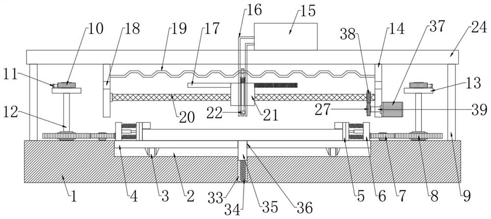
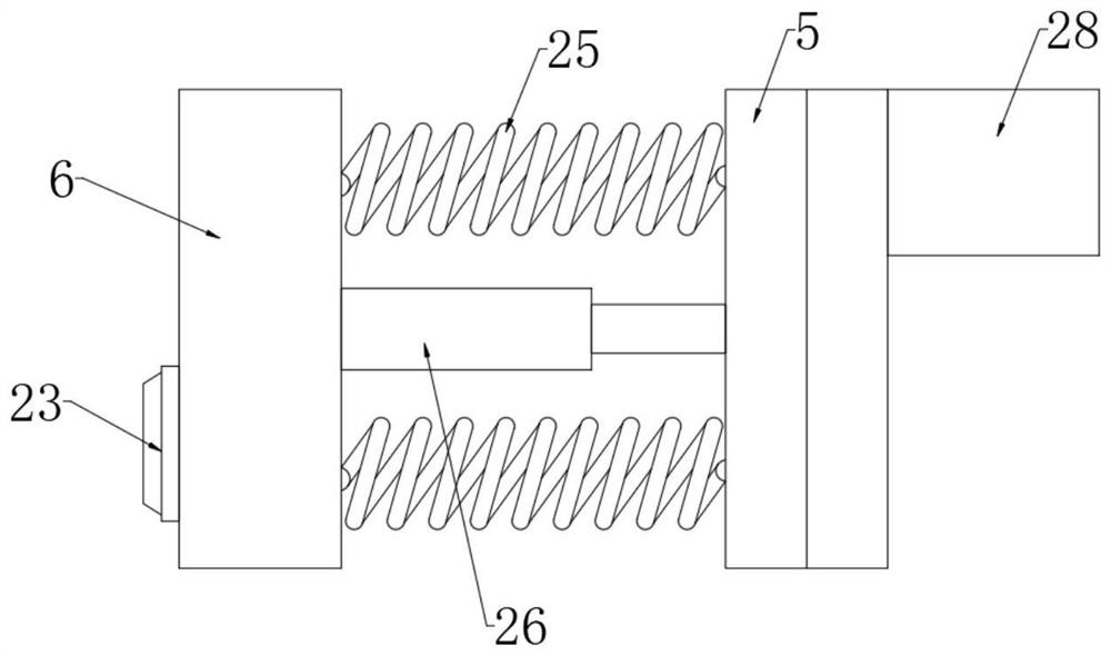
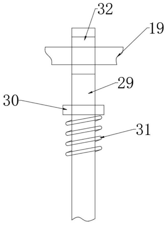
The invention discloses a circuit board pin dismounting processing device. The circuit board pin dismounting processing device comprises a workbench, wherein four supporting columns are fixedly connected to the workbench; the upper ends of the four supporting columns are jointly and fixedly connected with a top plate; two vertical plates are fixed at the bottom of the top plate; a zigzag-shaped rod is fixedly connected between the two vertical plates; a reciprocating screw rod is rotationally connected between the two vertical plates; a driving mechanism is arranged between the reciprocating screw rod and one vertical plate; a sliding block matched with the reciprocating screw rod is arranged on the reciprocating screw rod in a sleeving mode; a mounting rod which is in sliding connection with the sliding block is arranged on the sliding block in an up-down penetrating mode; and a through groove is formed in the upper end of the mounting rod in a penetrating mode. The circuit board pindismounting processing device is reasonable in structure, can automatically carry out hot melting on soldering tin points of pins on the two sides of a single-chip microcomputer and can suck away hot-melted soldering tin, so that the pins are not limited any more, the operation is convenient and rapid, the workload of workers is reduced, meanwhile, the dismounting efficiency of the single-chip microcomputer is high, and the harm to the bodies of the workers is also reduced.

Description

technical field [0001] The invention relates to the technical field of electronic equipment, in particular to a circuit board pin removal processing device. Background technique [0002] The names of the circuit boards are: ceramic circuit board, alumina ceramic circuit board, aluminum nitride ceramic circuit board, circuit board, PCB board, aluminum substrate, high frequency board, thick copper board, impedance board, PCB, ultra-thin circuit board, ultra-thin Thin circuit boards, printed circuit boards, etc. The circuit board makes the circuit miniaturized and intuitive, and plays an important role in mass production of fixed circuits and optimizing the layout of electrical appliances. Circuit boards can be called printed circuit boards or printed circuit boards. The birth and development of FPC circuit boards and rigid-flex boards FPC and PCB have given birth to the new product of rigid-flex boards. Therefore, the soft and hard combination board is the flexible circuit b...

Claims


Application Information

Patent Timeline
Patent Type & Authority Applications(China)
IPC IPC(8): B23K1/018B23K3/04B23K3/08
CPCB23K1/018B23K3/04B23K3/08
Inventor 卢康俊
Owner 四川久远智能消防设备有限责任公司
Learn More