A compression head and a compression device

A technology of a pressing device and a pressing head, which is applied to auxiliary devices, metal processing equipment, auxiliary welding equipment, etc., can solve the problems of scrapped mask 100', uneven surface, weak welding, etc.

Active Publication Date: 2022-02-18
SHANGHAI MICRO ELECTRONICS EQUIP (GRP) CO LTD
View PDF12 Cites 0 Cited by
  • Summary
  • Abstract
  • Description
  • Claims
  • Application Information

AI Technical Summary

Problems solved by technology

[0004] 1) When the mask 100' is welded to the frame 200', the metal at the welding point 130' melts, and the stress inside the mask 100' to resist the stretching of the stretching device 400' changes, thus causing the surface of the mask 100' to pattern moves, such as figure 2 As shown, the pattern moves from position one 110' to position two 120', thereby causing the mask 100' to be scrapped;
[0005] 2) if image 3 As shown, the surface of the frame 200' used to connect the mask 100' is uneven, with tiny pits 210', and the molten metal liquid flows to the gap between the mask 100' and the frame 200', so that the mask 100' and the frame The connection of 200' has the problem of weak welding or weak welding

Method used


Image

  • A compression head and a compression device
  • A compression head and a compression device
  • A compression head and a compression device

Examples


Embodiment 1

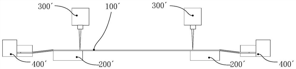
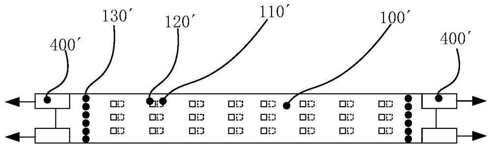
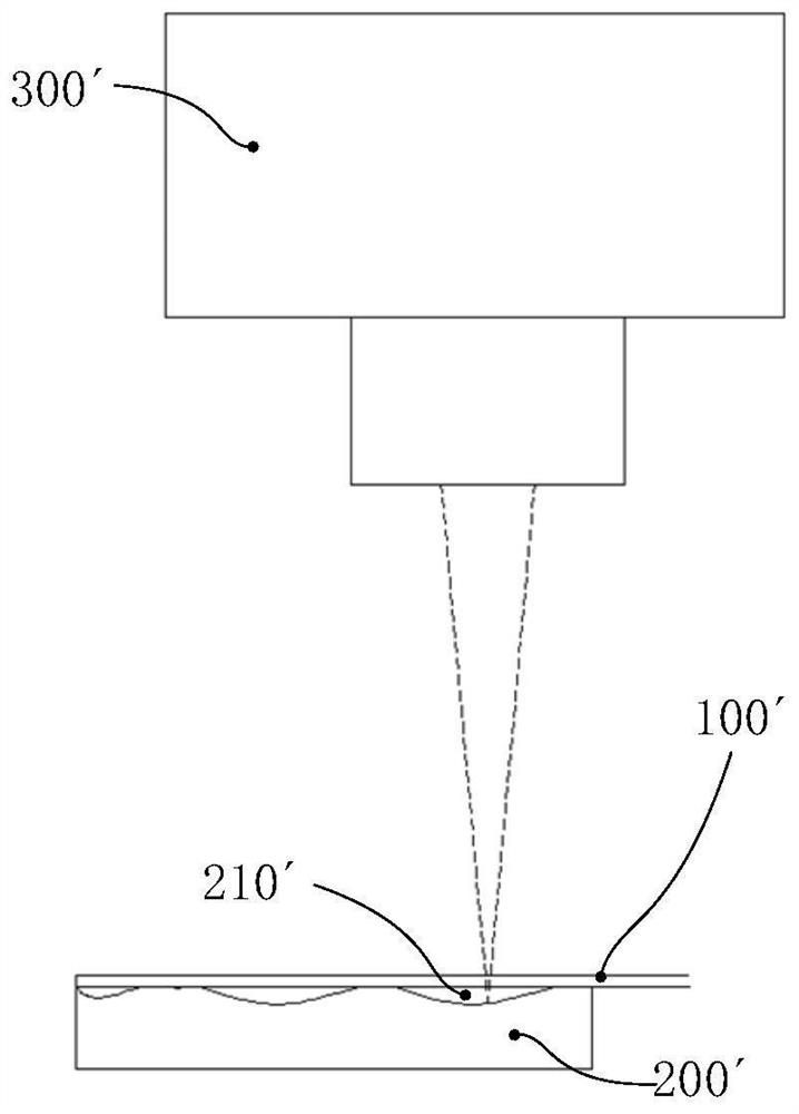
[0056] Such as Figure 4 As shown, this embodiment provides a pressing device, including a pressing head 10 and a driving mechanism 20 capable of driving the pressing head 10 to move, so that the pressing head 10 can move to the position where the object to be pressed needs to be pressed. Among them, the pressing device can be used in many welding fields, and this embodiment is used to illustrate the application of the pressing device to the welding of the mask 100 . The pressing head 10 mainly presses the mask 100 on the frame 200 connected thereto, and then uses the welding device 300 to perform welding.

[0057] Specifically, as Figure 5 and 6 As shown, the compression head 10 includes a mounting frame 11, and the mounting frame 11 is provided with a through hole 12 for the welding beam 310 to pass through; The elastic claws can contact the mask 100 and press it elastically. After the elastic claws press the mask 100 and the frame 200 tightly, the welding beam 310 gene...

Embodiment 2

[0067] Such as Figure 10 As shown, the structure of the compression head 10 in this embodiment is basically the same as that in Embodiment 1, the difference between the two is that the elastic claws of the compression head 10 in this embodiment are made of heat-resistant rubber 15, The heat-resistant rubber 15 itself has a certain degree of compressibility, and it can be directly snapped into the installation groove of the installation frame 11 , and there is no need to reserve a space 14 between the installation frame 11 and the installation frame 11 . Wherein the heat-resistant rubber 15 can be selected from nitrile rubber, fluorine rubber and the like.


PUM


Abstract

The invention discloses a compression head and a compression device, belonging to the technical field of welding. The pressing head includes a mounting frame, and the mounting frame is provided with a through hole for the welding beam to pass through; both sides of the through hole are provided with elastic pressure claws, and the elastic pressure claws are connected with the mounting frame. The elastic pressing claws can be in contact with the parts to be pressed and pressed elastically. The pressing device includes the above-mentioned pressing head. In the present invention, by setting the compression head, the stress change of the parts to be compressed cannot be transmitted to the stretching device during the welding process, thereby avoiding the phenomenon that the mask surface pattern moves and the mask plate is scrapped, and the elastic claws of the compression head can be The mask is closely attached to the frame with uneven surface, which solves the problem that the molten metal liquid flows in the frame with uneven surface, resulting in weak or false welding between the mask and the frame.

Description

technical field [0001] The invention relates to the field of welding technology, in particular to a pressing head and a pressing device. Background technique [0002] Currently, in the process of manufacturing the organic light-emitting layer of an OLED (Organic Light-Emitting Diode, Organic Light-Emitting Diode) display screen, a mask with a pattern is used to form a required pattern on an evaporation substrate by vacuum evaporation. The mask plate includes a mask and a frame. When the mask is combined with the frame, a stretching device is used to tension the mask on the frame, and then the mask is welded on the frame by a laser to form the required mask plate. [0003] Among them, such as figure 1 and 2 As shown, after the mask 100' is tensioned by the stretching device 400', the mask 100' and the frame are melted and welded at high temperature by a laser 300'. The inventor found in the process of connecting the mask 100' to the frame 200' that: [0004] 1) When the m...

Claims


Application Information

Patent Timeline
Patent Type & Authority Patents(China)
IPC IPC(8): B23K37/04
CPCB23K37/04B23K37/0443
Inventor 耿鹏飞张洪博徐健黄元昊罗闻罗兵
Owner SHANGHAI MICRO ELECTRONICS EQUIP (GRP) CO LTD
Why Eureka
Try Eureka