
Radius filler for wet composite layup

A radius, composite-based technology applied in the field of composite material manufacturing

Pending Publication Date: 2021-01-29
THE BOEING CO
View PDF0 Cites 0 Cited by
  • Summary
  • Abstract
  • Description
  • Claims
  • Application Information

AI Technical Summary

Problems solved by technology

While the above manufacturing methods are structurally advantageous, laminators represent a substantial capital expenditure in construction, operation and maintenance

Method used


Image

  • Radius filler for wet composite layup
  • Radius filler for wet composite layup
  • Radius filler for wet composite layup

Examples


Embodiment Construction

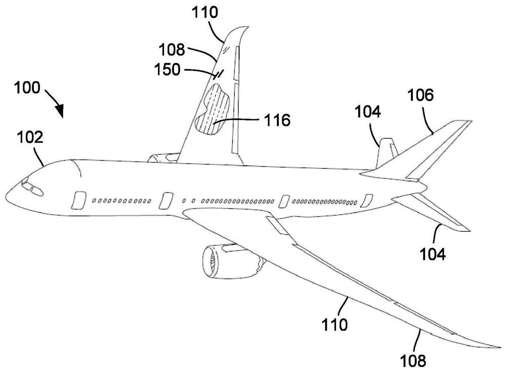
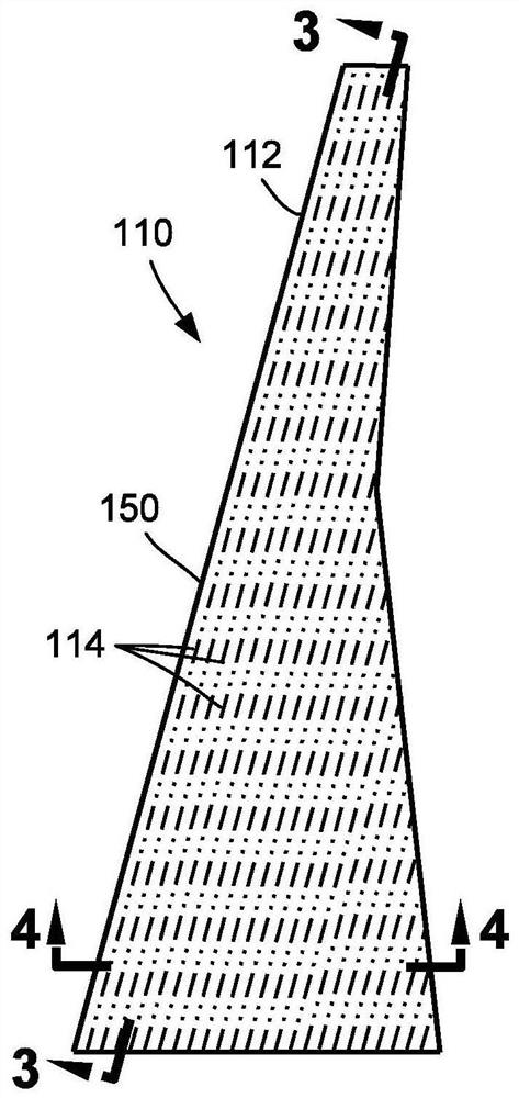
[0042] Referring now to the accompanying drawings illustrating preferred examples and various examples of the present disclosure, in figure 1 A perspective view of an aircraft 100 is shown in , which may include filler elements 200 having a radius (eg, Figure 5 ) of one or more cured composite structures 110 made of radius filler material 202 (e.g., Figure 5 ) were formed and fabricated as described below. Aircraft 100 may include a fuselage 102, a horizontal stabilizer 104, a vertical stabilizer 106, and a pair of wings 108, any one or more of which may be a cured composite structure 110 fabricated in accordance with one or more aspects of the present disclosure. For example, figure 1 The aircraft 100 in FIG. 1 may include one or more composite wing spars 116 each configured as a cured composite structure 110 . figure 2 A cured composite structure 110 configured as a wing panel 112 is shown having a composite skin panel 150 and a plurality of composite stringers 114 for...


PUM


Abstract

Disclosed is a radius filler for wet composite layup. A method of manufacturing a cured composite structure includes placing a radius filler element into a radius cavity extending along a length of acomposite base member formed of dry fiber material comprised of reinforcing fibers. The radius filler element is formed of a radius filler material. The method also includes infusing resin into the dry fiber material, and chemically reacting the resin with the radius filler material to create a mixture of resin and radius filler material along side surface interfaces between the radius filler element and the composite base member. The method additionally includes curing or solidifying the resin, and allowing solvent in the resin to evaporate causing hardening of the mixture and bonding of theradius filler element to the composite base member, and resulting in a cured composite structure.

Description

technical field [0001] The present disclosure relates generally to composite fabrication and, more particularly, to a composite structure having a thermoplastic or thermoset radius filler and a method of fabricating the composite structure. Background technique [0002] Composite structures are widely used in various applications due to their high strength-to-weight ratio, corrosion resistance, and other favorable properties. In aircraft construction, composite materials are increasingly used to form fuselages, wings and other components. For example, an aircraft wing may include composite skin panels reinforced by composite stringers. [0003] Composite stringers can be provided in various cross-sectional shapes. For example, a composite stringer of a wing panel may have a T-shaped cross-section formed by assembling a pair of composite channels (eg, L-shaped channels) in a back-to-back arrangement. Each compound channel includes a flange portion and a web portion joined ...

Claims


Application Information

Patent Timeline
IPC IPC(8): B29C70/48B29C70/54B29L31/30
CPCB29C70/48B29C70/54B29L2031/3085B64C1/061B33Y80/00B29D99/0014B29C70/70B29C70/72B29C70/44B64C2001/0072B64C3/18B64C1/12B64C3/20B64C3/24B29C70/549B29D99/0005B29C70/021B29K2105/12B29K2105/16B29C70/00B29C70/745B29C70/42B64C3/26B32B2260/046B32B5/12B32B2605/18B32B2260/023B32B1/00B32B5/26B32B5/145B32B2307/54
Inventor 斯坦利·斯塔夫斯基
Owner THE BOEING CO
Learn More