
Multi-element mixed work medium condensating, separating, throttling and oleep cooling circular refrigeration system

A multi-component mixed working medium, condensate separation technology, applied in refrigerators, refrigeration and liquefaction, compressors with cascade work, etc., can solve problems such as low separation efficiency, inability to separate liquids, and insufficient separation

Inactive Publication Date: 2003-10-01
中科赛凌(北京)科技有限公司
View PDF0 Cites 2 Cited by
  • Summary
  • Abstract
  • Description
  • Claims
  • Application Information

AI Technical Summary

Problems solved by technology

Compared with the primary throttling cycle refrigerator mentioned above, the internal cascade cycle refrigerator has a certain improvement in reliability, but its structure becomes complicated and not suitable for small devices, and because the gas-liquid separation is The flash separation under isothermal and isobaric conditions based on the phase equilibrium characteristics of zeotropic mixtures requires a mechanical separation method to separate the liquid phase from the high-pressure fluid at the separation point and throttle it back to the low-pressure channel. The separated liquid composition is the composition of the liquid phase in phase equilibrium at the separation point, and the separation result is determined by the temperature at the separation point and the phase equilibrium characteristics of the working medium (the temperature of the separated gas-liquid two-phase is equal), if the boiling points of adjacent components in the working medium are compared Close, there will be two problems, one is that the separation of high boiling point components is not thorough enough, there will still be more content into the next stage, and the other is that too much separation of components in the middle temperature zone will reduce the efficiency of the next stage and cause refrigeration The efficiency of the whole machine decreases; at the same time, the separation efficiency of the mechanical separation method is low, and the formed liquid cannot be completely separated

Method used


Image

  • Multi-element mixed work medium condensating, separating, throttling and oleep cooling circular refrigeration system
  • Multi-element mixed work medium condensating, separating, throttling and oleep cooling circular refrigeration system
  • Multi-element mixed work medium condensating, separating, throttling and oleep cooling circular refrigeration system

Examples


Embodiment 1

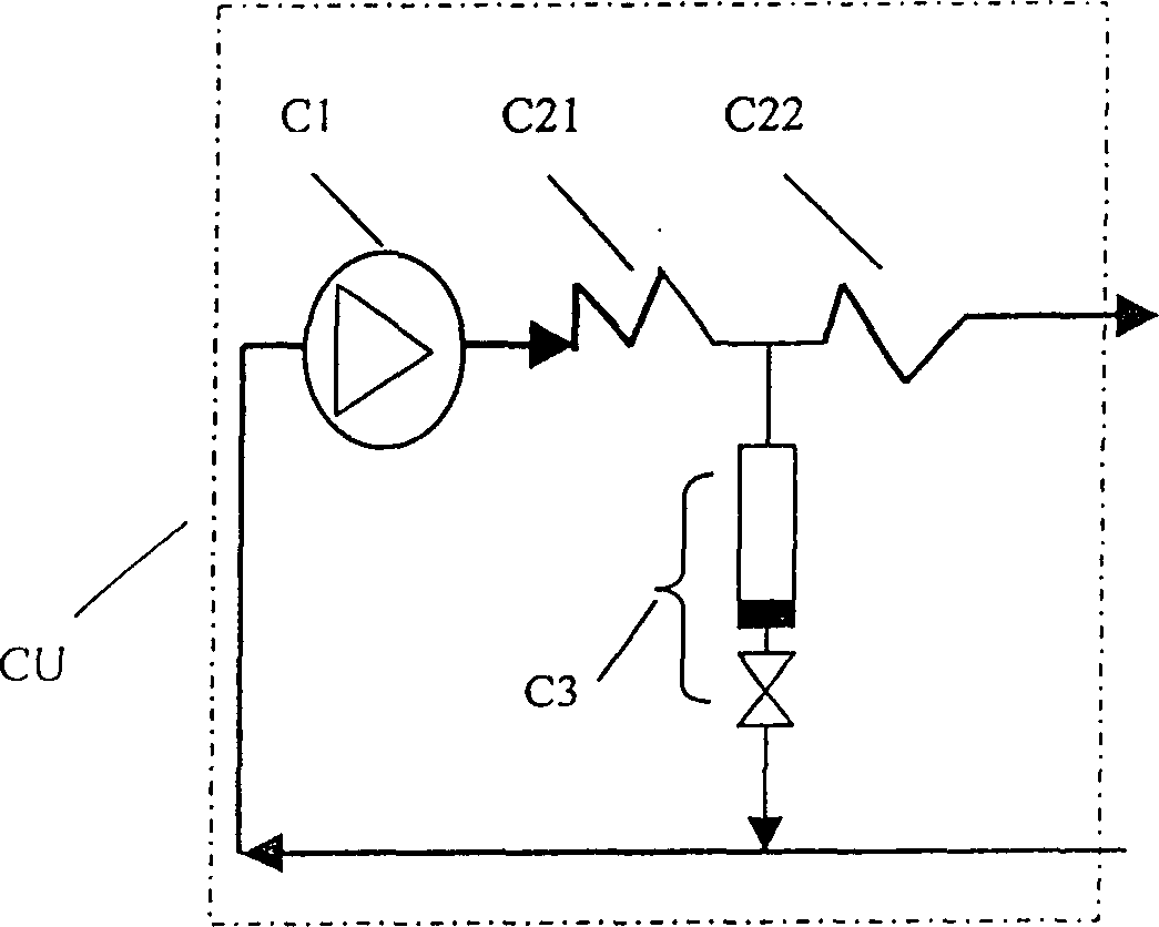
[0047] Embodiment 1: A single-stage oil-lubricated air-conditioning compressor is used to drive the refrigerating machine of the present invention to reach a temperature zone of 183K, and its structure diagram is shown in Image 6 . The specific structure of the compressor module is: the compressor C1 adopts a 1kW single-stage oil-lubricated air-conditioning compressor, the two pre-coolers C21 and C22 are conventional condensers, and the lubricating oil filter separator C3 is a conventional product. The connection method is as follows: The high-pressure outlet pipe of compressor C1 is connected to the inlet pipe of the first front cooler C21, and the outlet of C21 is connected with the inlet of the second front cooler C22 and the inlet of lubricating oil filter oil return device C3 through a three-way connecting pipe fitting, and is connected by the inlet of C22 The outlet constitutes the high-pressure outlet of the compressor module. The C3 outlet of the lubricating oil filte...

Embodiment 2

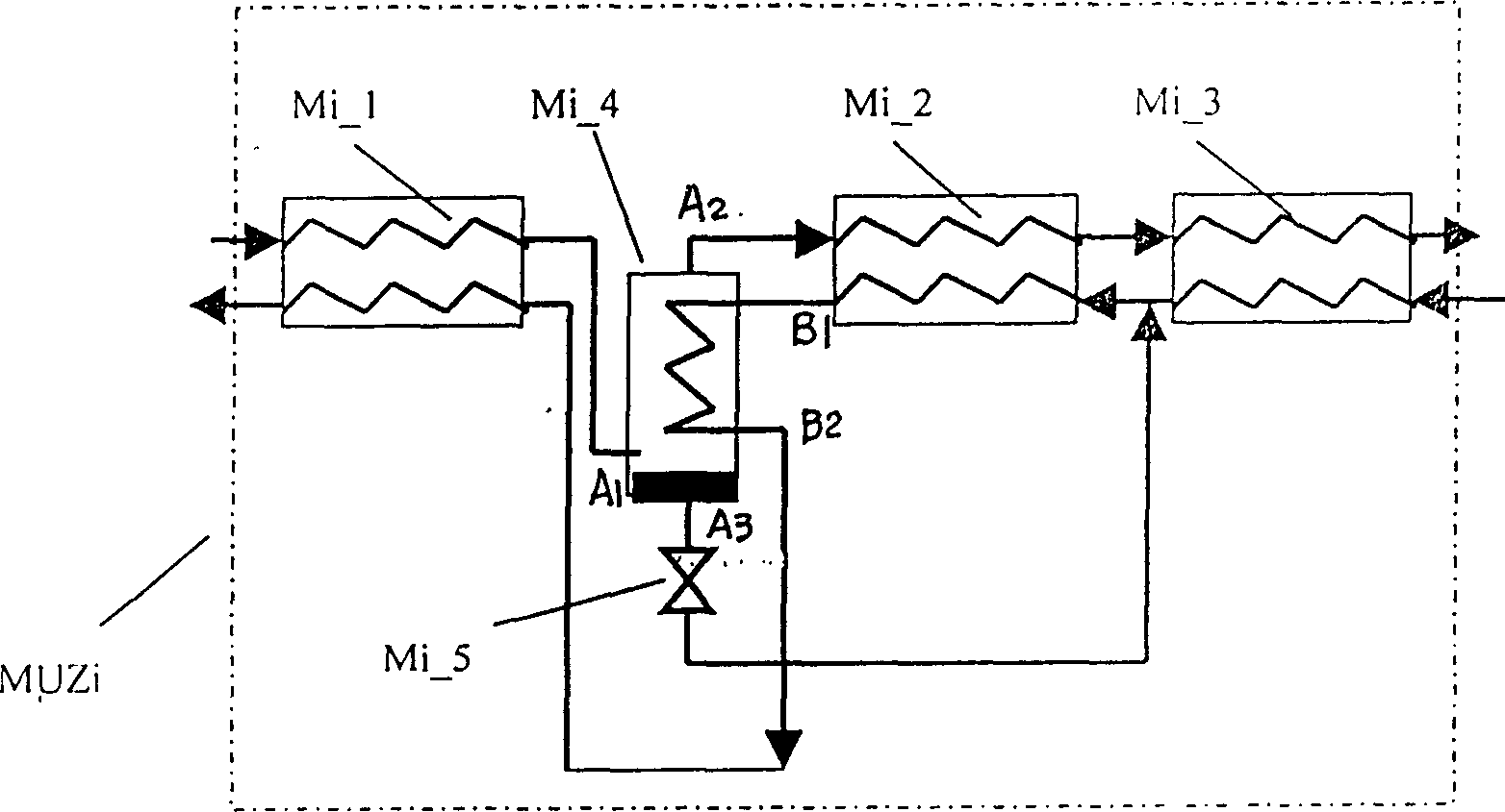
[0048] Embodiment 2: adopt the present invention to reach 120K temperature zone, its structural diagram sees Figure 7 . The structure of the compressor module is the same as in Embodiment 1. The intermediate refrigeration module MU adopts a three-stage mixed working medium refrigeration sub-module, in which the first-stage refrigeration sub-module MUZ1 includes a condensate separator M1_4, a throttling element M1_5 and its pipelines. The connection method is: the high-pressure outlet of the compressor module is connected to the The high-pressure inlet A1 of the condensing separator M1_4, the high-pressure liquid outlet A3 at the bottom of the condensing separator M1_4 are connected to the throttling element M1_5, the outlet of M1_5 is connected to the low-pressure inlet B1 of the condensing separator M1_4, the high-pressure gas outlet A2 of M1_4 is connected to the next-stage refrigeration module MUZ2 The high-pressure inlet is connected, and the low-pressure outlet B2 of th...

Embodiment 3

[0049] Embodiment 3: adopt the present invention to reach the liquid nitrogen temperature zone, see its structure Figure 8. The compressor module is the same as in Embodiment 1. The intermediate refrigeration module is composed of five-stage sub-modules, in which the first-stage mixed working medium refrigeration sub-module MUZ1 includes a decondensation separator M1_4, a throttling element M1_5, a pre-counterflow heat exchanger M1_1, and an intermediate counterflow heat exchanger M1_2. The method is: the high-pressure outlet of the compressor module is connected to the high-pressure inlet of the counterflow heat exchanger M1_1, the high-pressure outlet of M1_1 is connected to the high-pressure inlet of M1_4, the high-pressure gas outlet of M1_4 is connected to the high-pressure inlet of M1_2, and the high-pressure outlet of M1_2 is connected to the high-pressure The inlet is connected; the high-pressure separation liquid outlet of M1_4 is connected with the throttling eleme...


PUM


Abstract

The multi-component mixed working medium segregation, separation, throttling and throttling cryogenic refrigeration cycle system involved in the present invention includes a compressor, an intermediate refrigeration and an evaporator module; the compressor module is composed of a compressor, a front cooler and a filter oil return device; the intermediate refrigeration module It consists of multi-stage mixed working medium refrigeration sub-modules, each sub-module includes a decondensation separator, a throttling element and a counterflow heat exchanger; the evaporator module includes a throttling element, an evaporator and a counterflow heat exchanger; the refrigerator adopts a high-efficiency Multi-component non-azeotropic mixed working fluid, no environmental hazards, driven by a single compressor, simple and reliable, multi-component mixed working fluid internal cascade refrigeration, reliable performance of the refrigerator, high refrigeration efficiency.

Description

field of invention [0001] The invention relates to a refrigerator in the technical field of refrigeration and low temperature, in particular to a multi-component mixed working medium separation, separation, throttling, and throttling cryogenic refrigeration cycle system. Background technique [0002] The multi-element low-temperature mixed refrigerant primary throttling refrigerator developed in recent years is composed of a compressor, a cooler, a counterflow heat exchanger, an evaporator, and throttling elements. It has a simple structure, low cost, and relatively high thermal efficiency. However, due to the use of multiple non-azeotropic working fluids as the refrigerant, the temperature of the evaporator has a large slippage, and due to a throttling cycle, the lubricating oil carried by the refrigerant fluid enters the low-temperature end of the refrigerator, which is likely to cause blockage of the throttling element and low-temperature end heat exchangers and evaporato...

Claims


Application Information

Patent Timeline
Patent Type & Authority Patents(China)
IPC IPC(8): F25B7/00
Inventor 吴剑峰公茂琼罗二仓
Owner 中科赛凌(北京)科技有限公司
Learn More