Pit cover tipping device

A boring pit and turning mechanism technology, applied in the field of metallurgy, can solve problems such as poor stability of steel slag, aging and spalling of plant column cement, affecting column strength and rigidity, etc., achieves good separation effect of slag and steel, eliminates unstable factors, and improves The effect of grinding efficiency

Inactive Publication Date: 2021-01-29
鞍钢集团工程技术有限公司
View PDF7 Cites 0 Cited by
  • Summary
  • Abstract
  • Description
  • Claims
  • Application Information

AI Technical Summary

Problems solved by technology

[0004] The canning operation when the existing steel slag is hot-splashed causes the plant to shake, causing the steel structure of the plant to loosen and even the weld seam to crack; the hot-splashed dust causes the slag to accumulate and corrode the slag across the plant frame; the high-temperature red slag causes the cement of the plant column to age and peel off, affecting the strength and Rigidity; the slag-span factory building has great safety hazards
Steel slag splashing produces a large amount of dust and mist, and the operating conditions of the field equipment are poor, with large loss and high failure rate
[0005] The existing steel slag hot splash treatment process is a simple open treatment method, the air pollutants produced cannot be collected centrally, the air pollutants are discharged in an unorganized manner, and the dust on the job exceeds the standard; during the steel slag treatment process, the slag cross-air building smokes seriously, which is obvious Excessive discharge; steel slag cooling sewage has a small amount of discharge
[0006] The steel slag treated by hot splashing has poor separation effect between slag and steel, which increases the difficulty of subsequent screening and magnetic separation, resulting in the loss of iron resources; free magnesium oxide and free calcium oxide in steel slag cannot be digested, resulting in poor stability of steel slag and tailings It cannot be used as building materials, building material products and road materials, and the utilization rate is low

Method used


Image

  • Pit cover tipping device
  • Pit cover tipping device
  • Pit cover tipping device

Examples


Embodiment Construction

[0030] The specific embodiment of the present invention will be further described below in conjunction with accompanying drawing:

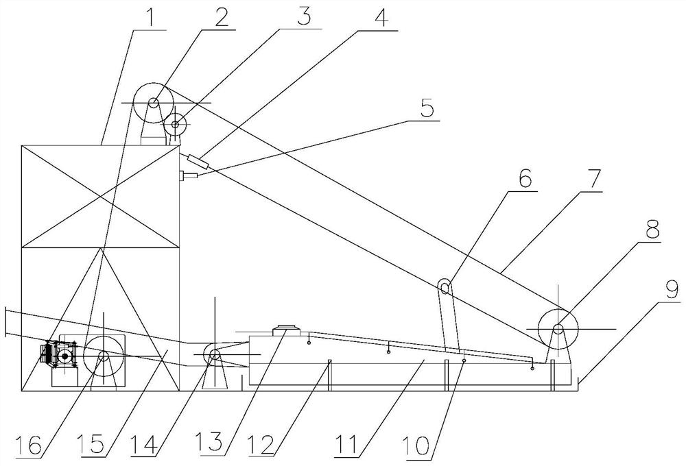
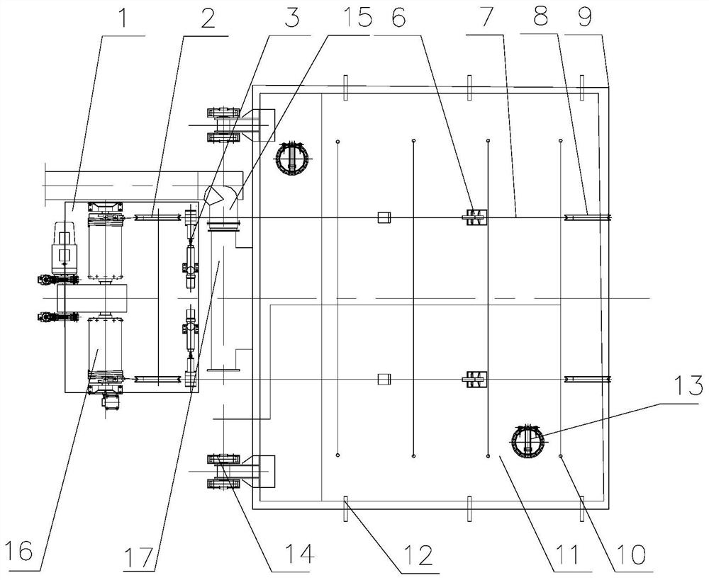
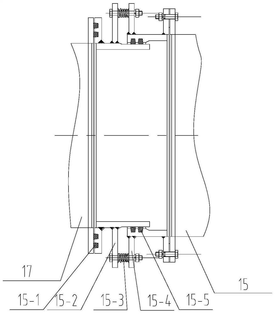
[0031] See Figure 1-Figure 5 , a pit cover tilting device, comprising a pulley overturning mechanism, a pit cover 11, a water seal groove 9, a stuffy cover water spray mechanism 10, and a smoke discharge pipe 15, one end of the pit cover 11 is hinged to the side of the stuffy pit, The pit cover 11 is flipped open and closed by the pulley turning mechanism, the water seal groove 9 is arranged around the pit cover 11 and the side of the boring pit, the pit cover 11 is provided with a smoke exhaust pipe joint 17, and the smoke Gas discharge pipe 15 is provided with smoke inlet pipe joint 15-4 (seeing image 3 ), the rotatable and sealed connection between the smoke exhaust pipe joint 17 and the smoke intake pipe joint 15-4, and a stuffy cover water spray mechanism 10 is provided on the inner wall of the pit cover 11 top.

[0032] The stuffy cover ...


PUM


Abstract

A pit cover tipping device comprises a pulley overturning mechanism, a pit cover, a water seal tank, a stuffy cover water spraying mechanism and a smoke discharging pipeline, one end of the pit coveris hinged to the edge of a stuffy pit, the pit cover is opened and closed in an overturning mode through the pulley overturning mechanism, the water seal tank is arranged on the periphery of the pit cover and the edge of the stuffy pit, and the pit cover is provided with a smoke discharging pipe connector. The smoke discharging pipeline is provided with a smoke inlet pipe connector, the smoke discharging pipe connector is connected with the smoke inlet pipe connector in a rotatable and sealed mode, and the stuffy cover water spraying mechanism is arranged on the inner wall of the top of the pit cover. The pit cover tipping device is mainly used for putting molten steel slag into a stuffy pit, covering the pit with the pit cover tipping device and spraying a small amount of water for cooling, or putting steel slag cooled to about 800 DEG C into a steel slag pit specified in design, covering the steel slag pit with a stuffy cover of the pit cap tipping device, spraying water mist after sealing, and digesting and self-pulverizing the steel slag, so that the steel slag is subjected to stabilizing treatment, resource utilization is facilitated, slag and iron are fully separated, and waste steel is conveniently recycled through magnetic separation.

Description

technical field [0001] The invention belongs to the field of metallurgy, in particular to a pit cover tipping device. Background technique [0002] The existing liquid steel slag treatment method in the steelmaking plant is: liquid steel slag is poured hot on the slag crossing site—turned to the pile—drawing water for cooling—shipment to the slag industry company. [0003] The solid steel slag treatment method is: the cold slag basin is dumped at the slag crossing site—electromagnetic suction cup magnetic separation—turning heap—drawing water for cooling—shipment to the slag industry company. [0004] The canning operation when the existing steel slag is hot-splashed causes the plant to shake, causing the steel structure of the plant to loosen and even the weld seam to crack; the hot-splashed dust causes the slag to accumulate and corrode the slag across the plant frame; the high-temperature red slag causes the cement of the plant column to age and peel off, affecting the st...

Claims


Application Information

Patent Timeline
Patent Type & Authority Applications(China)
IPC IPC(8): C21B3/08
CPCC21B3/08C21B2400/068C21B2400/024Y02P10/20
Inventor 王玉王爽金洪廉刘化建谷金生王昆刘浩岳文龙
Owner 鞍钢集团工程技术有限公司
Why Eureka
Try Eureka