Steep inclined shaft slip form system and cast-in-place concrete lining construction method

A construction method and concrete technology, applied in shaft lining, tunnel lining, earthwork drilling and mining, etc., to achieve the effects of improving efficiency, preventing water accumulation, and improving efficiency and quality

Inactive Publication Date: 2021-01-29
浙江世润建创科技发展有限公司
View PDF0 Cites 0 Cited by
  • Summary
  • Abstract
  • Description
  • Claims
  • Application Information

AI Technical Summary

Problems solved by technology

[0004] The purpose of the present invention is to provide a slipform system for steeply inclined shafts and a construction method for cast-in-place concrete lining, which solves the existing problems

Method used


Image

  • Steep inclined shaft slip form system and cast-in-place concrete lining construction method
  • Steep inclined shaft slip form system and cast-in-place concrete lining construction method
  • Steep inclined shaft slip form system and cast-in-place concrete lining construction method

Examples


Embodiment Construction

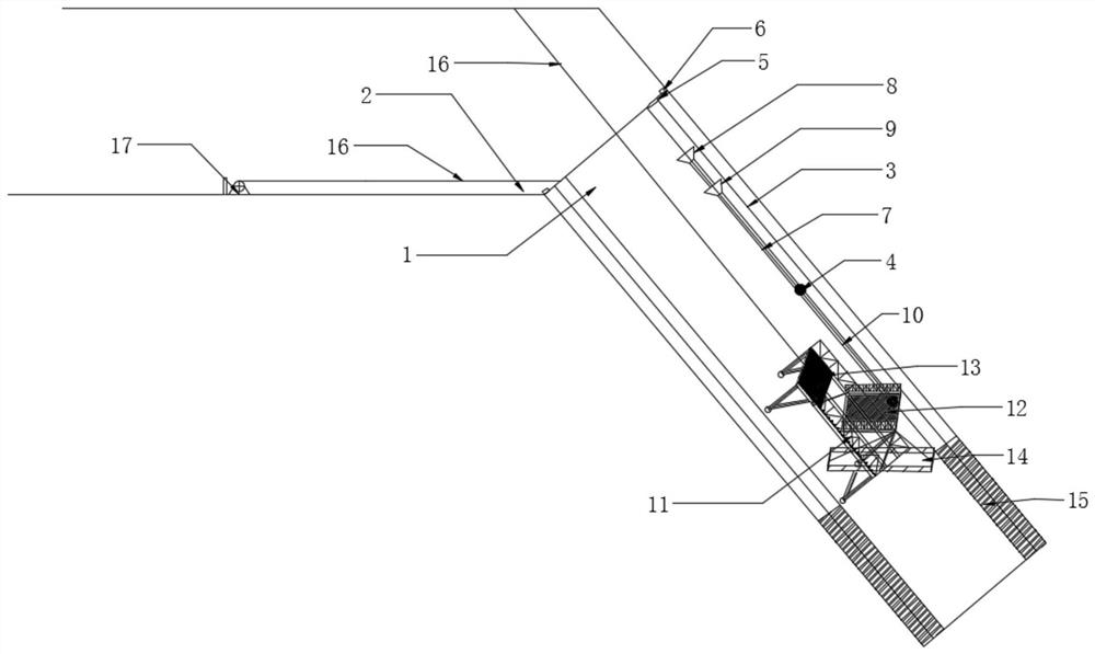
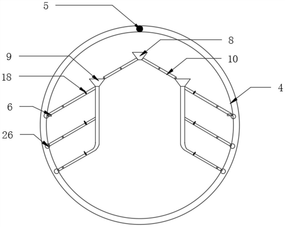
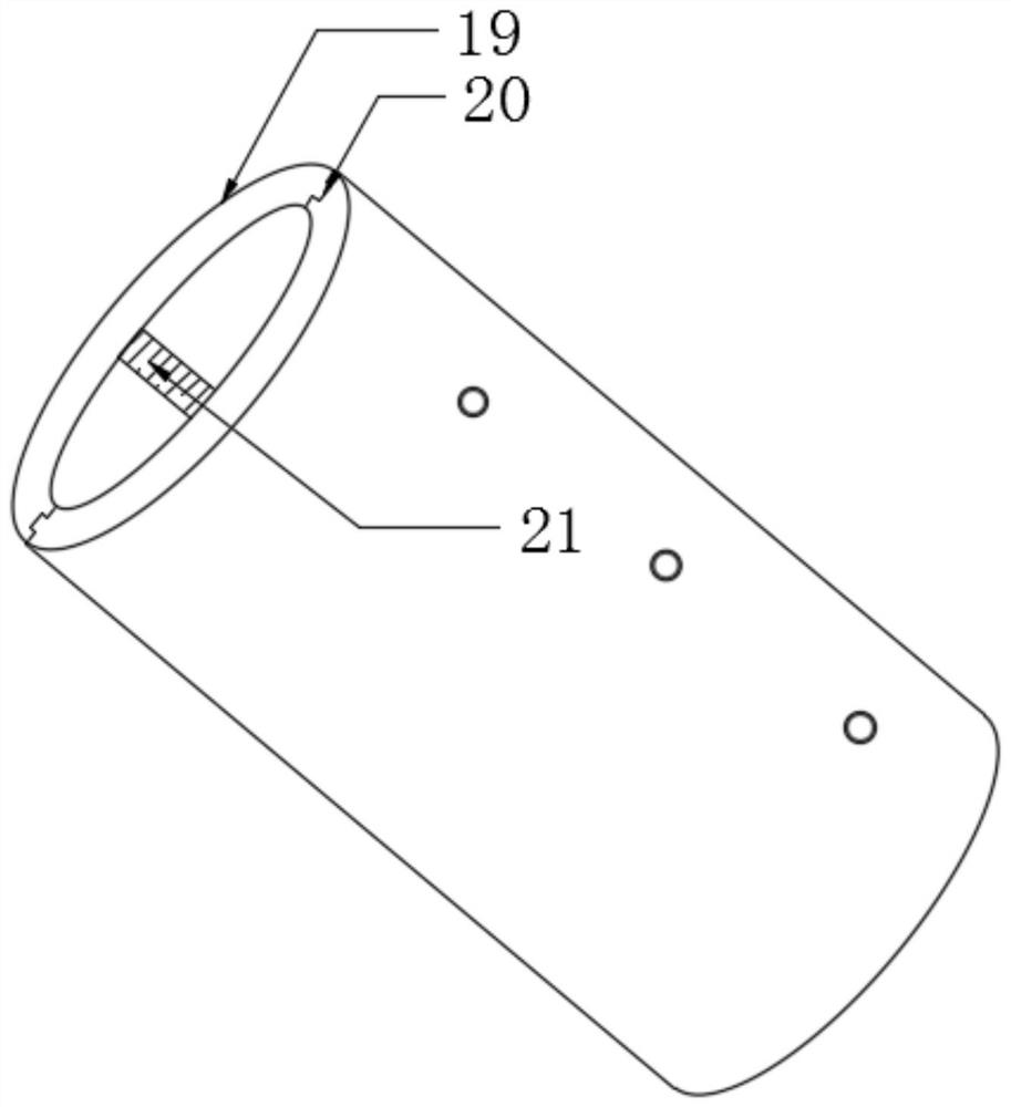
[0043] The following will clearly and completely describe the technical solutions in the embodiments of the present invention with reference to the accompanying drawings in the embodiments of the present invention. Obviously, the described embodiments are only some, not all, embodiments of the present invention. Based on the embodiments of the present invention, all other embodiments obtained by persons of ordinary skill in the art without creative efforts fall within the protection scope of the present invention.

[0044] In describing the present invention, it is to be understood that the terms "opening", "upper", "lower", "thickness", "top", "middle", "length", "inner", "surrounding" etc. Indicating orientation or positional relationship is only for the convenience of describing the present invention and simplifying the description, and does not indicate or imply that the components or elements referred to must have a specific orientation, be constructed and operated in a sp...


PUM


Abstract

The invention discloses a steep inclined shaft slip form system and a cast-in-place concrete lining construction method, and belongs to the technical field of steep inclined shaft concrete construction. The construction method comprises the steps that construction preparation is carried out, and specifically, a winch, a prefabricated separation type steel form, and a lifting vehicle which are needed by construction are prepared; form body mounting is carried out, specifically, the separation type steel form is aligned and folded according to a rabbet and then is lowered to an inclined shaft, and the lifting vehicle is adjusted and placed in the separation type steel form to be adjusted; chute mounting is carried out, and specifically, a chute at the customized pouring device communicates with a chute pouring window preset on the separated steel form; and concrete pouring is carried out, and specifically, concrete is poured into the concrete pump pouring window by using a concrete pumpto fill a gap between the separation type steel form and the inclined shaft; and chute pouring is carried out while concrete pouring is carried out, and a lifting trolley is lifted through a winch toconvey workers to conduct quality inspection on a poured section. Inner wall pouring of the steep inclined shaft is completed through the above steps, maintenance is carried out through a spraying device, and the service life of the inclined shaft is prolonged.

Description

technical field [0001] The invention belongs to the technical field of concrete construction for steeply inclined shafts, in particular to a sliding form system for steeply inclined shafts and a construction method for cast-in-situ concrete lining. Background technique [0002] Inclined shafts are used as auxiliary tunnels for extra-long tunnels. With the development of society, there are more and more inclined shafts. Inclined shafts can not only increase the working surface for the construction of the main tunnel, but also serve as a temporary or permanent ventilation channel during the construction of the main tunnel. Multi-directional closure of the construction lead to improve construction accuracy. [0003] In the process of concrete construction, the construction must be carried out with one plate followed by one plate and two linings, and the trolley can only be moved when the concrete is completely solidified, so the slip-form construction cannot meet the requiremen...

Claims


Application Information

Patent Timeline
Patent Type & Authority Applications(China)
IPC IPC(8): E21D11/10E21F16/00
CPCE21D11/102E21D11/105E21F16/00
Inventor 王新泉阮艳婷
Owner 浙江世润建创科技发展有限公司
Why Eureka
Try Eureka