Switching device and its manufacturing method, phase change random access memory

A switching device and manufacturing method technology, applied in the field of memory, can solve the problems affecting the yield and reliability of the device, deteriorating the electrical performance of the device, and failing to work normally, and achieve the effects of reducing the impact ionization rate and improving the HCI effect.

Active Publication Date: 2022-05-13
YANGTZE MEMORY TECH CO LTD
View PDF5 Cites 0 Cited by
  • Summary
  • Abstract
  • Description
  • Claims
  • Application Information

AI Technical Summary

Problems solved by technology

In the existing technology, in order to meet the requirements of high-voltage and low-voltage devices at the same time, the thickness of the sidewall is 80nm, and the thickness of the gate is 130nm, which has reached the limit, but there is still HCI effect, which leads to the degradation of the electrical performance of the device, and the device cannot work normally. work, affecting device yield and reliability

Method used


Image

  • Switching device and its manufacturing method, phase change random access memory
  • Switching device and its manufacturing method, phase change random access memory
  • Switching device and its manufacturing method, phase change random access memory

Examples


Embodiment Construction

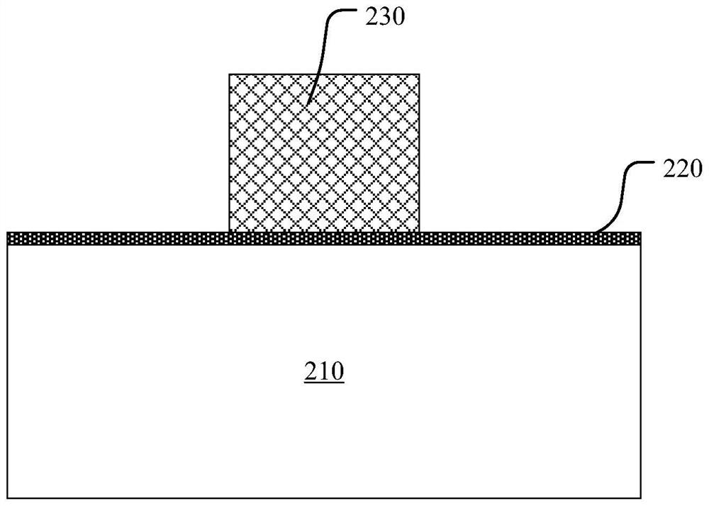
[0027] Hereinafter, the present invention will be described in more detail with reference to the accompanying drawings. In the various figures, identical elements are indicated with similar reference numerals. For the sake of clarity, various parts in the drawings have not been drawn to scale. Also, some well-known parts may not be shown. For the sake of simplicity, the semiconductor structure obtained after several steps can be described in one figure.

[0028] It should be understood that when describing the structure of a device, when a layer or a region is referred to as being "on" or "over" another layer or another region, it may mean being directly on another layer or another region, or Other layers or regions are also included between it and another layer or another region. Also, if the device is turned over, the layer, one region, will be "below" or "beneath" the other layer, or region.

[0029] If it is to describe the situation directly on another layer or anothe...


PUM

PropertyMeasurementUnit
thicknessaaaaaaaaaa
thicknessaaaaaaaaaa

Abstract

A method for manufacturing a switching device is disclosed, comprising: forming an insulating layer on a substrate; forming a patterned gate conductor on the insulating layer; forming sidewalls on the surface of the gate conductor and forming side walls on both sides of the gate conductor Forming the source region and the drain region in the substrate includes: forming a first sidewall on the surface of the gate conductor, forming a first doped region in the substrate on both sides of the first sidewall; forming a first sidewall on the surface of the first sidewall Two sidewalls, forming a second doped region in the first doped region on both sides of the second sidewall; forming a third sidewall and a fourth sidewall in sequence on the surface of the second sidewall; forming on both sides of the fourth sidewall A third doped region is formed in the second doped region, and a fourth doped region is formed in the third doped region, wherein the doping doses of the first doped region to the fourth doped region are sequentially Increase. In the phase-change random access memory of the present application, a more slowly changing PN junction can be obtained by performing multiple ion implantations during the formation of the sidewall, thereby reducing the impact ionization rate and improving the HCI effect.

Description

technical field [0001] The invention relates to the technical field of memory, in particular to a switch device and a manufacturing method thereof, and a phase-change random access memory. Background technique [0002] Phase Change RAM (PCPAM) changes the phase change layer inserted between the top electrode and the bottom electrode to a crystalline or amorphous state through a current flowing between the top electrode and the bottom electrode. The information stored in the cell is read using the difference between the resistance of the phase change layer in the crystalline state and the resistance of the phase change layer in the amorphous state. [0003] In PCRAM devices, the high-voltage devices (5.0V) in the peripheral circuit have high requirements for Hot Carrier Injection (HCI), so thicker side walls and gate thickness are required; but at the same time, in order to improve the I / The transmission speed of the O interface requires faster low-voltage devices (1.2V) in...

Claims


Application Information

Patent Timeline
Patent Type & Authority Patents(China)
IPC IPC(8): H01L45/00
CPCH10N70/253H10N70/231H10N70/011
Inventor 甘程
Owner YANGTZE MEMORY TECH CO LTD
Why Eureka
Try Eureka