Electric spraying device for medical adhesive
A spraying device and electric technology, applied in the field of medical devices, can solve the problems of long time, complicated operation steps, and the medical glue is not light and thin enough, and achieve the effect of good glue forming effect and uniform mixing effect.
- Summary
- Abstract
- Description
- Claims
- Application Information
AI Technical Summary
Problems solved by technology
Method used
Image
Examples
Embodiment 1
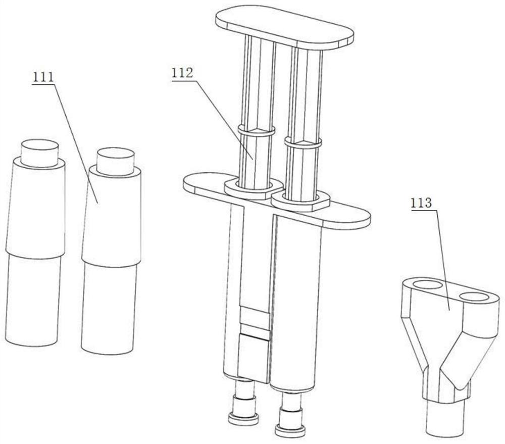
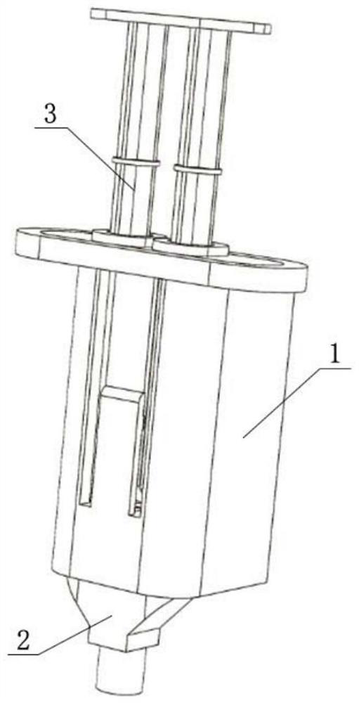
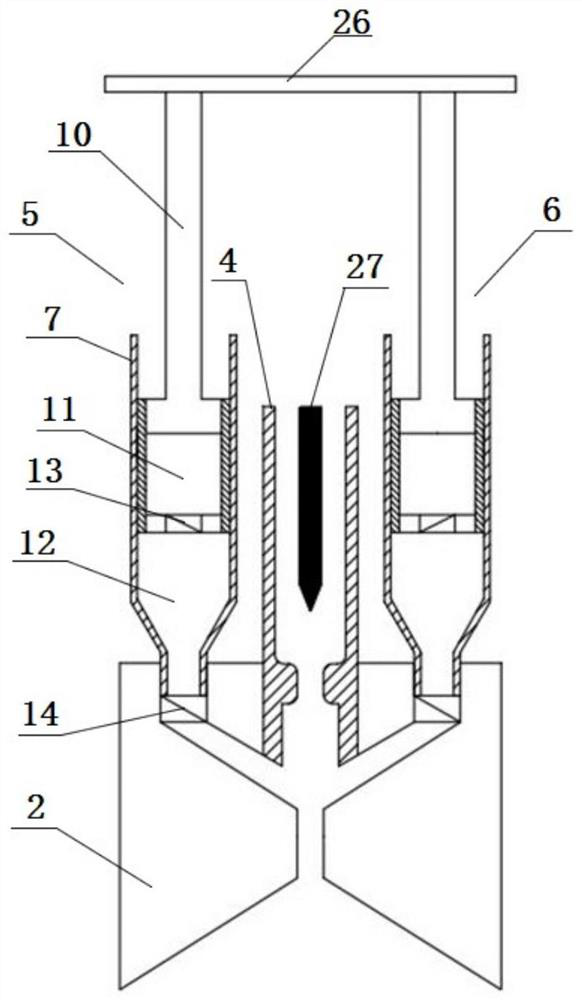
[0041] Such as figure 2 and image 3 Shown, a kind of medical glue electric spraying device, wherein, comprise shell 1, be located at the shower head 2 of described shell 1 one end, be used for the multi-component injector 3 that each basic component of medical glue is packaged separately, and The high-pressure gas unit communicated with the internal passage of the shower head 2, the high-voltage electrostatic unit arranged on the shower head 2, and the control unit for controlling the high-pressure gas unit and the high-voltage electrostatic unit; the multi-component injector 3 is connected from the The other end of the casing 1 is inserted inside the casing 1 and connected with the spray head 2 . Medical glue generally includes four basic components. The design of the present invention can separate and store the four basic components in one multi-component syringe through pre-filling, and then mix and cross-link the basic components when needed. At the same time, the high...
Embodiment 2
[0050] This embodiment is similar to Embodiment 1, the difference is that, as Figure 5 As shown, the blocking member 9 is slidingly and sealingly connected to the inner wall of the opening end of the barrel 7, and the syringe operating rod assembly 10 includes a side fixed to the side of the blocking member 9 close to the opening end of the barrel 7. The connected operating rod body 101 and the electromagnet 102 arranged on the side of the blocking member 9 close to the opening end of the barrel 7 and passing through the operating rod body 101, the circumference of the piston member 8 An annular iron component 81 is provided on the side wall. Like this, the first storage chamber 11 is made of the piston part 8, the blocking part 9 and the cylinder 7 wall between them equally, and the second storage chamber 12 is made of the side wall and the bottom wall of the piston part 8 and the cylinder 7 closed ends. constitute. When in use, first turn on the power supply of the electr...
Embodiment 3
[0052] This embodiment is similar to Embodiment 1, the difference is that, as Figure 6 and Figure 7 As shown, the blocking member 9 is fixedly connected to the end surface of the opening end of the barrel 7, one end of the syringe operating rod assembly 10 is fixedly connected to the piston member 8, and the other end extends through the blocking member 9. Out of the open end of the barrel 7, a spring bottle 15 is arranged in the first storage chamber 11, the mouth of the spring bottle 15 is connected with the first valve 13, and the syringe operating rod assembly 10 It is arc-shaped, the outer arc surface of the syringe operating rod assembly 10 is attached to the inner wall of the barrel 7 , and the inner arc surface of the syringe operating rod assembly 10 is attached to the outer wall of the spring bottle 15 . In this way, the first storage chamber 11 used for liquid storage is actually the spring bottle 15 , and the second storage chamber 12 is formed by the side wall ...
PUM
 Abstract
Description
Claims
Application Information
 - R&D
- Intellectual Property
- Life Sciences
- Materials
- Tech Scout
- Unparalleled Data Quality
- Higher Quality Content
- 60% Fewer Hallucinations
Browse by: Latest US Patents, China's latest patents, Technical Efficacy Thesaurus, Application Domain, Technology Topic, Popular Technical Reports.
© 2025 PatSnap. All rights reserved.Legal|Privacy policy|Modern Slavery Act Transparency Statement|Sitemap|About US| Contact US: help@patsnap.com


