
Differential centrifugal ceramic forming machine

A technology of ceramic molding machine and differential speed centrifugation, which is applied to ceramic molding machines, unloading devices, manufacturing tools, etc. It can solve problems such as cracking and damaging products, difficulty in mold opening, and cracking of mud products, so as to avoid the generation of air bubble pinholes , It is convenient to open the mold and take out the product, avoiding the effect of inconsistent shrinkage

Inactive Publication Date: 2021-02-02
李慧
View PDF3 Cites 1 Cited by
  • Summary
  • Abstract
  • Description
  • Claims
  • Application Information

AI Technical Summary

Problems solved by technology

[0003] In the existing grouting molding method, the mud is prone to produce air bubbles and pinholes, which will damage the surface of the product. The uneven shrinkage of the mud will cause stress to cause the product to crack, and it is difficult to open the mold, resulting in the product being destroyed when the mold is opened and taken out.
[0004] In order to solve the above problems, the inventor provides a differential speed centrifugal ceramic molding machine, which has the advantages of avoiding pinhole air bubbles and stress cracking to damage the product, and the advantages of easy mold opening

Method used


Image

  • Differential centrifugal ceramic forming machine
  • Differential centrifugal ceramic forming machine
  • Differential centrifugal ceramic forming machine

Examples


Embodiment Construction

[0022] The following will clearly and completely describe the technical solutions in the embodiments of the present invention with reference to the accompanying drawings in the embodiments of the present invention. Obviously, the described embodiments are only some, not all, embodiments of the present invention. Based on the embodiments of the present invention, all other embodiments obtained by persons of ordinary skill in the art without making creative efforts belong to the protection scope of the present invention.

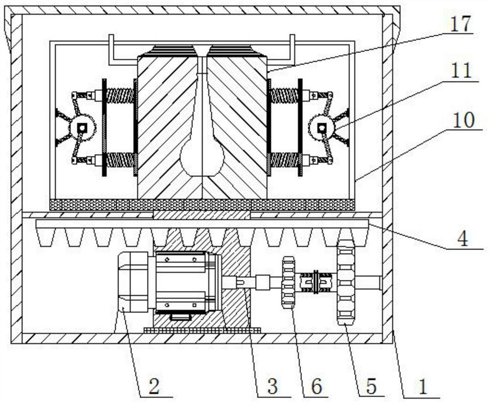
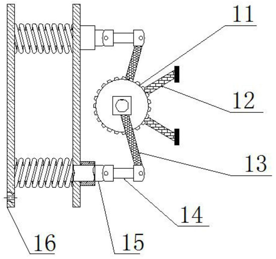
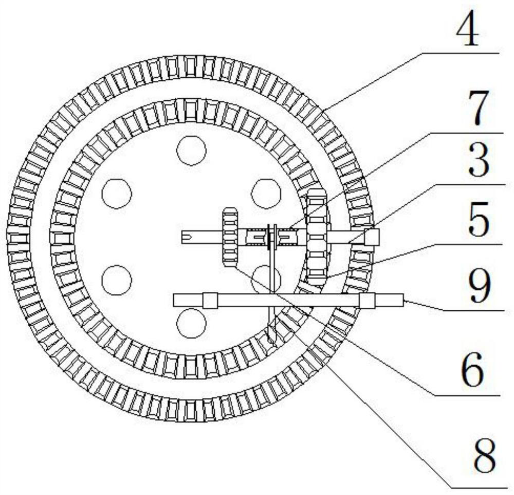
[0023] see Figure 1-4 , a differential centrifugal ceramic molding machine, comprising a frame 1, the inner bottom of the frame 1 is movably connected with a motor 2, the right side of the motor 2 is movably connected with a drive shaft 3, and the drive shaft 3 A shaft sleeve 7 is movably connected above, and the shaft sleeve 7 is connected with the driving shaft 3 by a key. The shaft sleeve 7 can move left and right on the driving shaft 3. The shaft sleeve 7...


PUM


Abstract

The invention relates to the technical field of ceramic forming, and discloses a differential centrifugal ceramic forming machine. The machine comprises a rack, a motor is movably connected to the inner bottom of the rack, and a driving shaft is movably connected to the right side of the motor. A shaft sleeve is movably connected to the upper surface of the driving shaft, and a high-speed gear ismovably connected to the right side of the shaft sleeve. The left side of the shaft sleeve is movably connected with a low-speed gear, and the middle of the shaft sleeve is movably connected with a paddle shift. Slurry is made to abut against the mold wall to form a compact blank through centrifugal force generated by rotation driven by a gear disc, bubbles are concentrated in the middle and finally broken out, and generation of bubbles and pinholes in a product is avoided. The slurry suction speed and the product quality are improved, few large particles can be concentrated on the surface ofthe blank due to differential centrifugation, and inconsistent shrinkage caused by uneven tissue is avoided. During mold opening, a clamping gear rotates reversely, clamping plates move outwards to pull a mold open, and the product can be taken out conveniently through mold opening under the displacement and extrusion effect of compressed air.

Description

technical field [0001] The invention relates to the technical field of ceramic molding, in particular to a differential speed centrifugal ceramic molding machine. Background technique [0002] Ceramic molding is the process of making products with a certain shape and size from the prepared blanks by various methods. In terms of technology, ceramic molding methods can be divided into grouting molding, plastic molding and compression molding according to the performance and water content of the blank. [0003] In the existing grouting molding method, the mud is prone to produce air bubbles and pinholes, which will damage the surface of the product. The uneven shrinkage of the mud will cause stress to cause the product to crack, and it is difficult to open the mold, resulting in the product being destroyed when the mold is opened and taken out. [0004] In order to solve the above problems, the inventor provides a differential speed centrifugal ceramic molding machine, which h...

Claims


Application Information

Patent Timeline
IPC IPC(8): B28B1/20B28B7/00B28B13/06
CPCB28B1/20B28B7/00B28B13/06
Inventor 李慧
Owner 李慧
Learn More