

Electric adjusting device for truck fairing
A technology of electric adjustment and shroud, applied in the direction of electromechanical devices, electric components, car body, etc., can solve the problems of affecting the operation stability, large driving resistance, high stress of parts, etc., and achieve good reliability, compact structure and precise movement Effect
- Summary
- Abstract
- Description
- Claims
- Application Information
AI Technical Summary
Problems solved by technology
Method used
Image

Examples
Embodiment 1
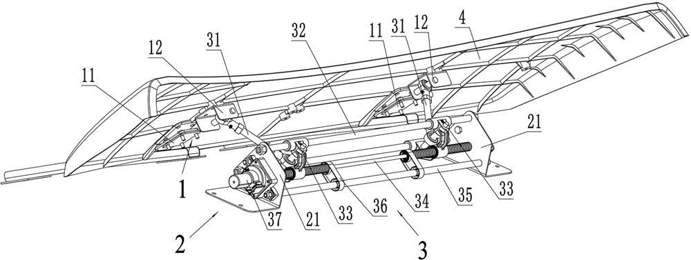
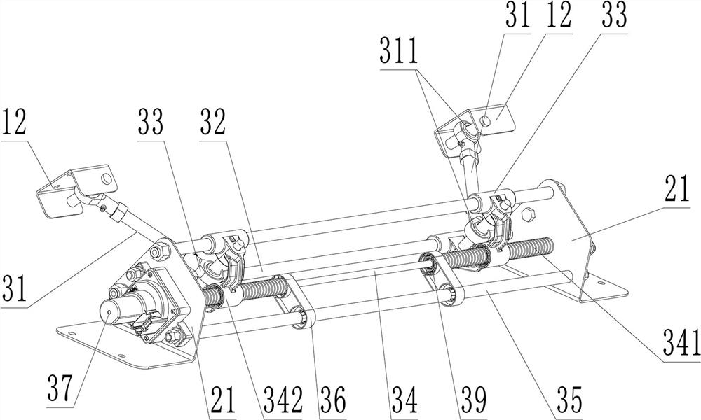
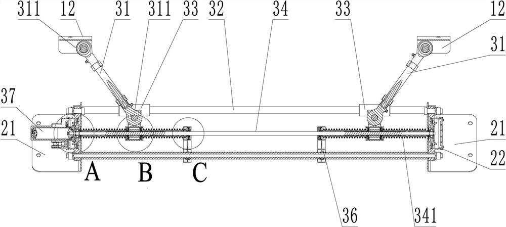
[0025] This embodiment is the optimal embodiment of the concept of the present invention. The electric adjustment device for the truck spoiler mainly includes a drive assembly 3 , a support assembly 2 and a support assembly 1 . Wherein, the support assembly 2 includes a pair of brackets 21; the support assembly 1 includes a linkage plate 12 for fixing the wind deflector 4; The two-way lead screw 34 that is arranged on the output end of the reduction motor 37, the two leading rods 32 that are arranged in the same direction as the two-way lead screw 34, the screw nuts 342 that are respectively positioned on both sides of the two-way lead screw 34 and that cooperate with the screw The connecting rod 31 hinged by the nut 342 is provided with a guide 33 on the leading rod 32 that cooperates with the screw nut 342 ; the other end of the connecting rod 31 is hingedly matched with the linkage plate 12 . In the same direction as the two-way leading screw 34, a guiding rod is also provi...
Embodiment 2
[0030]This embodiment is a sub-optimal embodiment of the present invention, and the purpose of setting this embodiment is to expand the protection scope of the present invention as much as possible. On the premise that the same technical problem can be basically solved, the driving assembly 3 in the first embodiment is omitted to some extent. Specifically, the guiding rod 35 is omitted, and the structure of the positioning plate 36 is simplified (for example, as long as it can be used for the sliding range of the screw nut 342 and can be fixed on the structure of the two-way lead screw 34), the original plan The waist circular structure is designed in order to cooperate with the guiding rod 35, and the figure is omitted. Based on the original intention of the design, those skilled in the art are motivated to simplify the structure to reduce the manufacturing cost without affecting the fluency of operation.
PUM
 Abstract
Description
Claims
Application Information