
Dry oil centralized lubrication system

A centralized lubricating and dry oiling technology, applied in lubricating parts, lubricating oil control valves, engine lubricating, etc., can solve problems such as oil shortage, blockage, burning loss of lubricating parts, and achieve the effect of preventing equipment damage

Active Publication Date: 2021-02-02
SHANGHAI MEISHAN IRON & STEEL CO LTD
View PDF5 Cites 1 Cited by
  • Summary
  • Abstract
  • Description
  • Claims
  • Application Information

AI Technical Summary

Problems solved by technology

At present, the centralized lubrication system of the reel has a major disadvantage: the pressure control valve is a signaling device that uses the differential pressure signal to convert it directly into an electrical signal. In fact, it is a pressure relay, which is specially used to control the reversing of the reversing valve. Installed at the end of the two oil supply main pipelines of the dry oil centralized lubrication system
Due to the limited number of oil holes in the rotary joint, coupled with the high-speed rotation of the reel and the high temperature inside the reel, the pressure control valve can only be installed on the main line close to the rotary joint, and cannot be installed at the end of the system in a real sense, in the pipeline The phenomenon of "dead oil" is easy to occur, and most of the distributors in the system are installed in parallel. If the main pipe or branch pipe of any distributor is blocked, although it does not affect the operation of the system, it cannot be found effectively and in time, and it is easy to cause oil shortage in the lubricating parts. burnout occurs
There are also related solutions in the prior art, but they can only be used in the shutdown state, and cannot achieve the purpose of online oil replenishment

Method used


Image

  • Dry oil centralized lubrication system
  • Dry oil centralized lubrication system
  • Dry oil centralized lubrication system

Examples


Embodiment 1

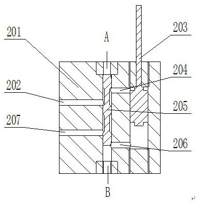
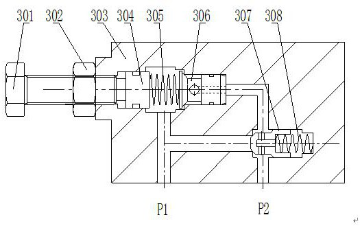
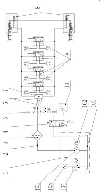
[0022]Example 1: seefigure 1 , A dry oil centralized lubrication system, the lubrication system includes a pump station assembly 1, a one-way valve 2, a filter 3, a two-position three-way electromagnetic reversing valve 4, a two-position four-way electromagnetic reversing valve 5, a flow meter 6. Rotary joint 7, one-way unloading valve 8, two-line distributor 9, pressure relay 10, and PLC control cabinet for controlling the pumping station, the pumping station assembly 1, one-way valve 2, filter 3, two-position three Two-way solenoid reversing valve 4, two-position four-way solenoid reversing valve 5, flow meter 6 are installed around the reel, rotary joint 7 is installed at the end of the reel; two one-way unloading valves 8 and multiple double lines The distributor 9 is installed inside a high-speed rotating drum. The pump station assembly 1 is connected to a one-way valve 2 and a two-position three-way electromagnetic reversing valve 4 at the same time. The one-way valve 2 is con...


PUM


Abstract

The invention relates to a dry oil centralized lubrication system which comprises a pump station assembly, a one-way valve, a filter, a two-position three-way electromagnetic reversing valve, a two-position four-way electromagnetic reversing valve, flow meters, a rotary joint, one-way unloading valves, double-line distributors, a pressure relay and a PLC control cabinet for controlling a pump station; the pump station assembly, the one-way valve, the filter, the two-position three-way electromagnetic reversing valve, the two-position four-way electromagnetic reversing valve and the flow metersare installed around a winding drum, and the rotary joint is installed at the tail end of the winding drum; and the two one-way unloading valves and the plurality of double-line distributors are installed in the winding drum which rotates at a high speed. According to the technical scheme, by designing the minimum number of pipelines, the one-way unloading valve is additionally arranged behind the last distributor, two cavities of the distributor are connected, although a pressure operating valve is installed beside the pump station, the pressure operating valve is actually located at the tail end of the pipeline, closed control over the system is achieved, and the phenomenon of dead oil in the dry oil system is eliminated.

Description

Technical field[0001]The invention relates to a lubrication system, in particular to a dry oil centralized lubrication system, belonging to the technical field of automatic centralized lubrication systems.Background technique[0002]The function of the reel is to roll the steel plate into a steel coil. The expansion and contraction mechanism of the reel is mainly composed of a hollow shaft and a fan-shaped plate surrounding the hollow shaft. In the hollow shaft, there is a mandrel connected to the hydraulic cylinder. The fan-shaped plate is connected to the mandrel by two connecting rods, and two oblique wedges are installed between each fan-shaped plate and the mandrel. When the piston rod of the hydraulic cylinder extends, it will push the mandrel to move through the connecting rod. The role of the fan-shaped plate is retracted, and the diameter of the reel is reduced accordingly. When the piston rod of the hydraulic cylinder is retracted, the mandrel will be pulled back, and then t...

Claims


Application Information

Patent Timeline
Patent Type & Authority Applications(China)
IPC IPC(8): F16N7/38F16N23/00F16N25/02F16N29/04
CPCF16N7/38F16N23/00F16N25/02F16N29/04
Inventor 袁亚东吴索团
Owner SHANGHAI MEISHAN IRON & STEEL CO LTD
Learn More