Automatically adjustable heat dissipation device for video distributor

A technology of video distributor and heat dissipation device, which is applied to measurement devices, electrical devices, televisions, etc., can solve the problems of heat discharge, wear, and poor heat dissipation effect of the video distributor, and achieves the problem of increasing the connection area and enhancing the heat dissipation efficiency. Effect

Inactive Publication Date: 2021-02-02
广州圣希悦贸易有限公司
View PDF0 Cites 2 Cited by
  • Summary
  • Abstract
  • Description
  • Claims
  • Application Information

AI Technical Summary

Problems solved by technology

When there are many output devices, the video splitter is in a high-load working state, and the electronic components inside it will generate a lot of heat, which will increase the temperature inside the splitter shell. However, most existing video splitters are sealed or There are small heat dissipation holes, so the heat cannot be discharged from the casing in time, and the heat dissipation effect is poor. Over time, the electronic components will be damaged and the service life of the video distributor will be shortened; there are also some distributors equipped with cooling fans. The heat dissipation effect is achieved, but the fan speed ca

Method used


Image

  • Automatically adjustable heat dissipation device for video distributor
  • Automatically adjustable heat dissipation device for video distributor
  • Automatically adjustable heat dissipation device for video distributor

Examples


Embodiment Construction

[0027] The technical solutions in the embodiments of the present invention will be clearly and completely described below with reference to the accompanying drawings in the embodiments of the present invention. Obviously, the described embodiments are only a part of the embodiments of the present invention, but not all of the embodiments. Based on the embodiments of the present invention, all other embodiments obtained by those of ordinary skill in the art without creative efforts shall fall within the protection scope of the present invention.

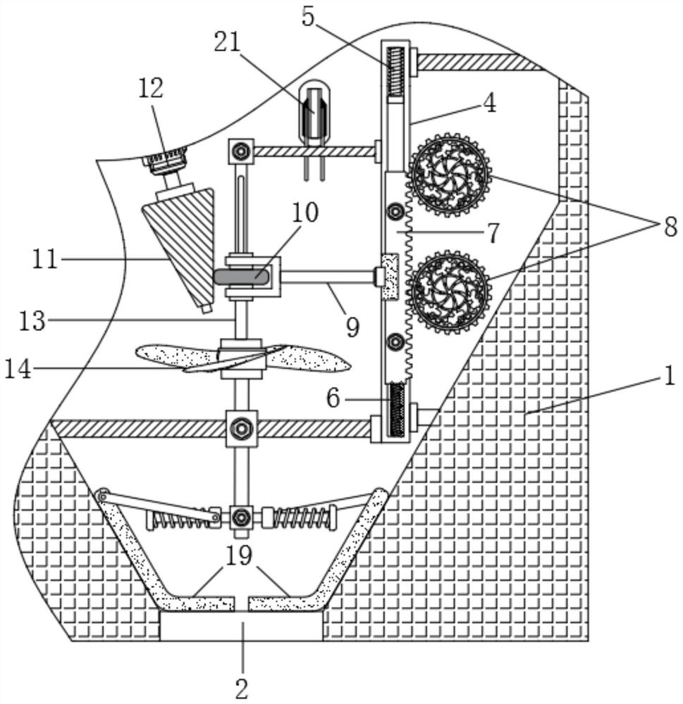
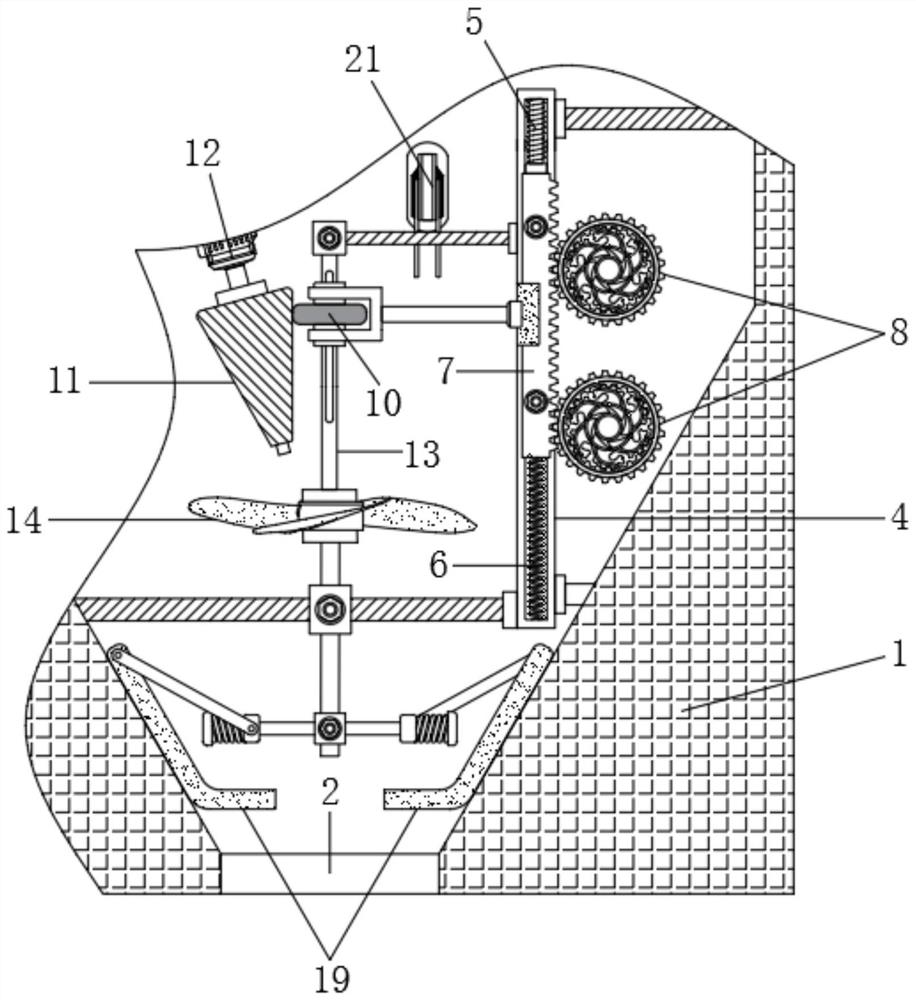
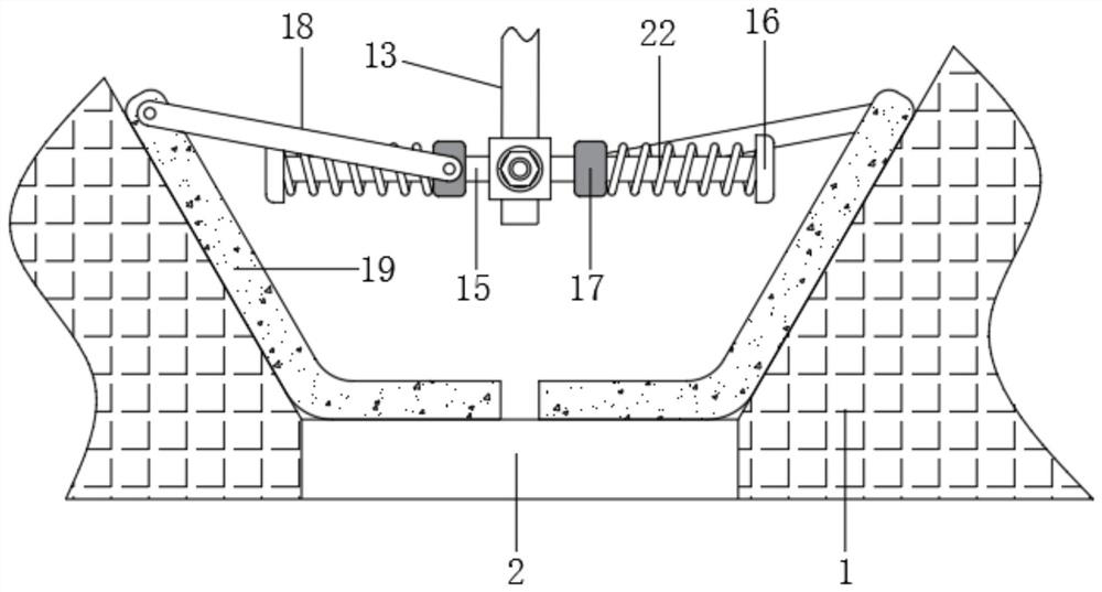
[0028] see Figure 1-6 , an automatically adjustable video distributor cooling device, comprising a shell 1, the bottom of the shell 1 is provided with cooling holes 2, the shell body of the shell 1 is provided with air intake holes 3, there are two air intake holes 3, An iris mechanism 20 is provided on the side of the air inlet 3 close to the inside of the casing 1, and the iris mechanism 20 includes six diaphragm plates and a fixed...


PUM


Abstract

The invention relates to the technical field of closed-circuit television monitoring systems, and discloses an automatically adjustable heat dissipation device for a video distributor. The heat dissipation device comprises a shell, wherein heat dissipation holes are formed in the bottom of the shell, air inlet holes are formed in a shell body of the shell, a sliding rail is arranged in and fixedlyconnected with the shell, an electromagnet is fixedly connected to the upper end of the sliding rail, a first spring is fixedly connected to the lower end of the sliding rail, and a metal rack is slidably connected to a sliding groove of the sliding rail. According to the automatically adjustable heat dissipation device for the video distributor, when the rotating speed of a sliding rod is increased, a gravity block slides in a direction towards a limiting block along the sliding rod, baffles are driven by a guide rod to slide upwards along the inner wall of the shell, and the lower ends of the two baffles are gradually far away from each other, so a communicating area of the heat dissipation holes and the interior of the shell is increased; and at the same time, the opening degree of airinlet holes and the rotating speed of a fan are increased, so the air flow in the shell is enhanced, and the effect of enhancing heat dissipation efficiency is achieved.

Description

technical field [0001] The invention relates to the technical field of closed-circuit television monitoring systems, in particular to an automatically adjustable cooling device for a video distributor. Background technique [0002] CCTV monitoring system is a multi-functional and all-round monitoring and highly intelligent processing system, which is used to provide long-distance monitoring and control. The CCTV monitoring system includes security cameras, TV monitors, image processors and video distributors. [0003] The video distributor is a device that evenly distributes a video signal source into multiple video signals. It can be used in the monitoring system to transmit the image of a security camera to multiple managers for viewing without changing the definition. When there are many output devices, the video distributor is in a high-load working state, and the electronic components inside will generate a lot of heat, which will increase the internal temperature of th...

Claims


Application Information

Patent Timeline
IPC IPC(8): H05K7/20H05K5/02G01K7/22G01K1/14H04N5/268
CPCG01K1/14G01K7/22H04N5/268H05K5/0213H05K7/20172H05K7/20209
Inventor 何伯韬
Owner 广州圣希悦贸易有限公司
Why Eureka
Try Eureka