Computer case stamping and feeding device and operation method

A feeding device, computer case technology, applied in the direction of feeding device, positioning device, storage device, etc., can solve the problems of restricting punching speed, existence safety, low efficiency, etc., and achieve stable feeding action, safe use, and convenient operation Effect

Active Publication Date: 2021-02-05
重庆化工职业学院
View PDF5 Cites 4 Cited by
  • Summary
  • Abstract
  • Description
  • Claims
  • Application Information

AI Technical Summary

Problems solved by technology

[0002] In the stamping process of the computer case, the feeding method seriously restricts the punching speed. The traditional manual feeding method is even more inefficient. The operator not only needs to take and unload the material, but also has to operate the machine tool. Not only is the efficiency low, but there are also potential safety hazards.

Method used


Image

  • Computer case stamping and feeding device and operation method
  • Computer case stamping and feeding device and operation method
  • Computer case stamping and feeding device and operation method

Examples


Embodiment Construction

[0020] Below according to accompanying drawing and embodiment the present invention will be described in further detail:

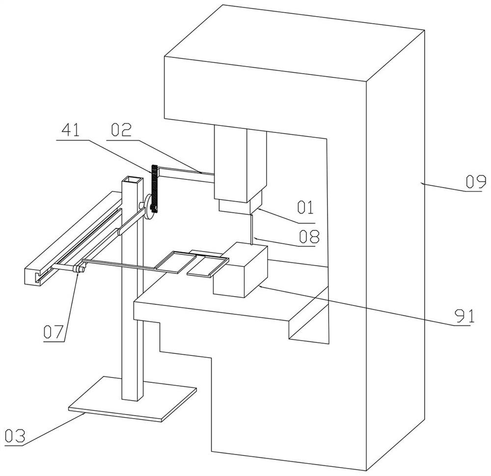
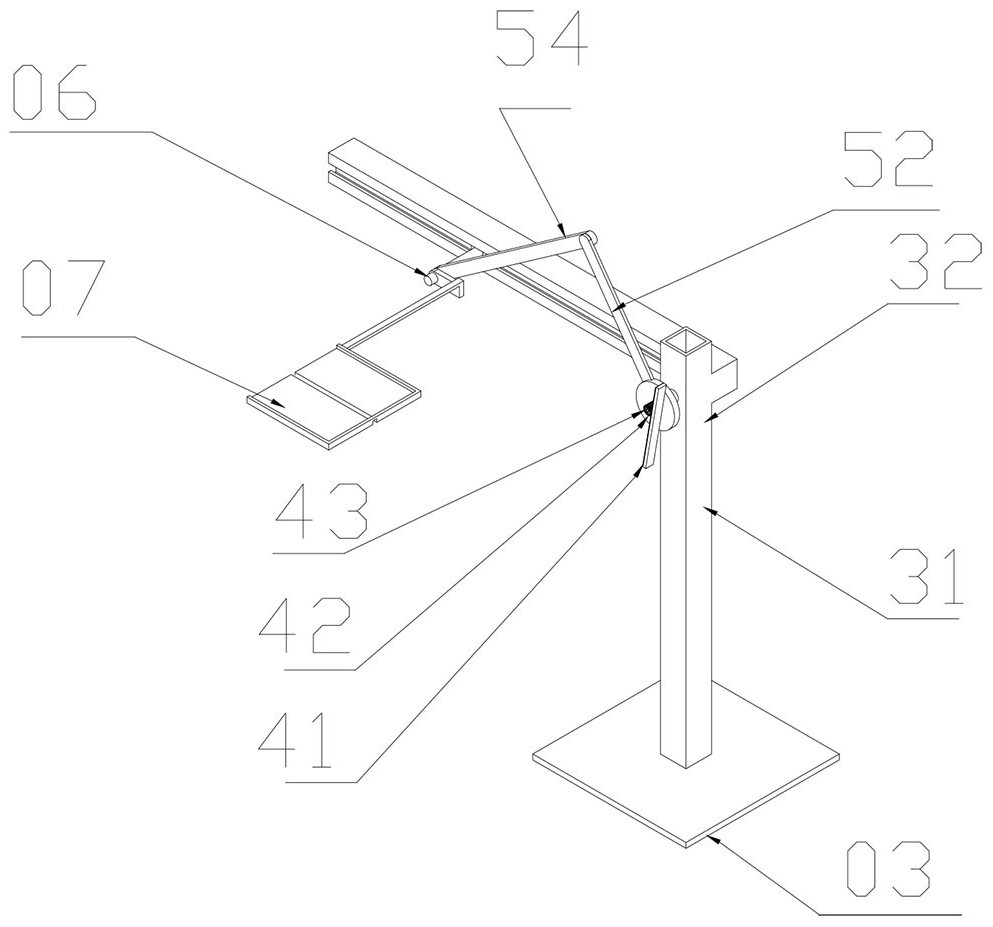
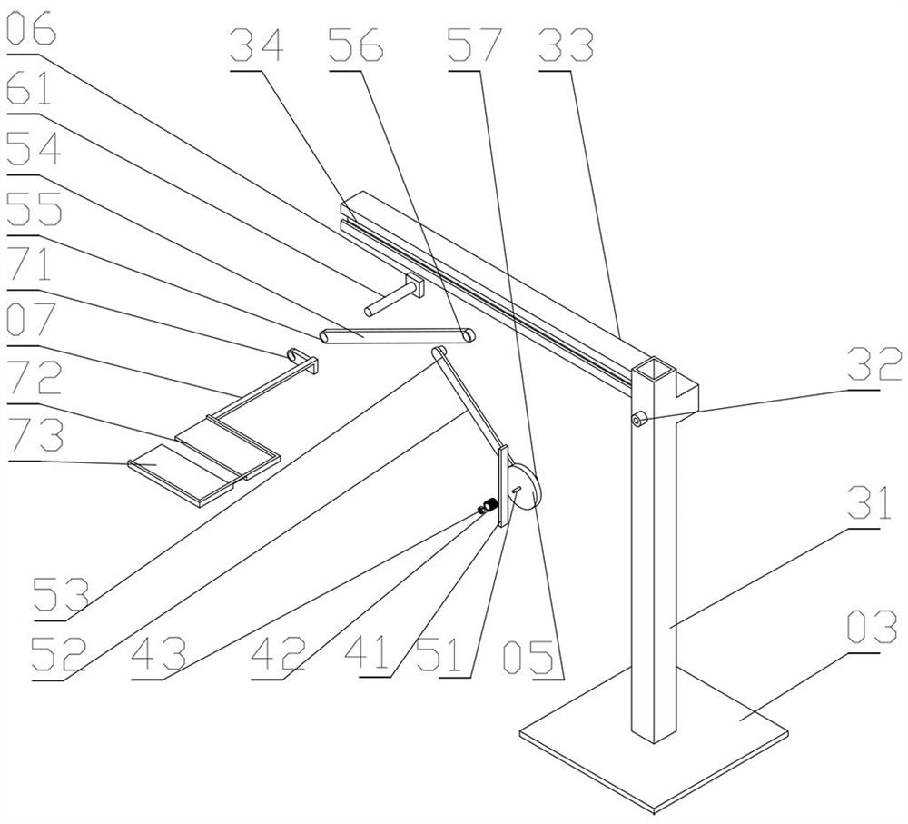
[0021] A punching and feeding device for a computer case, including a punching machine 09, a punch 01, a connecting arm 02, a frame 03, a chute 34, a rack 41, a gear 42, a one-way bearing 43, a crank 05, a slider 06, and a feeding tray 07. The upper part of the stamping machine tool 09 has a mold base 91, one side of the mold base 91 is connected to the positioning pin 08, the middle part of the stamping machine tool 09 is connected to the frame 03, the upper part of the frame 03 has a column 31, and the upper part of the column 31 has a fixing hole 32, behind the fixing hole 32 There is a slider seat 33 on the side, a chute 34 is arranged in the middle of the slider seat 33, a crank 05 is arranged in the middle of the fixing hole 32, a crank shaft 57 is arranged on the rear side of the crank 05, and the crank shaft 57 is connected to the fixing hole 32 in ...


PUM


Abstract

The invention discloses a computer case stamping and feeding device and an operation method. The computer case stamping and feeding device comprises a stamping machine tool, a punch, a connecting arm,a machine frame, a sliding groove, a rack, a gear, a one-way bearing, a crank, a sliding block and a feeding disc; a mold seat is arranged at the upper part of the stamping machine tool; a positioning pin is connected to one side of the mold seat; the machine frame is connected to the middle of the stamping machine tool; a stand column is arranged at the upper part of the machine frame; a fixinghole is formed in the upper part of the stand column; a sliding block seat is arranged on the back side of the fixing hole; a sliding groove is formed in the middle of the sliding block seat; the crank is arranged in the middle of the fixing hole; a crank rotating shaft is arranged on the back side of the crank; the crank rotating shaft is rotationally connected with the fixing hole; the crank rotating shaft rotates in the fixing hole; a crank arm is arranged on the left side of the crank; a connecting rod shaft is arranged on the left side of the crank arm; a second hole is formed in the right side of a connecting rod and is rotationally connected with the connecting rod shaft; and the connecting rod shaft rotates in the second hole.

Description

technical field [0001] The invention relates to the field of computer case processing, in particular to a stamping and feeding device and an operation method for a computer case. Background technique [0002] In the computer case stamping process, the feeding method seriously restricts the punching speed. The traditional manual feeding method is even more inefficient. Operators not only have to take and unload materials, but also operate the machine tool. Not only is the efficiency low, but there are also potential safety hazards. Contents of the invention [0003] The present invention aims at the above-mentioned deficiencies existing in the prior art, and provides an efficient and automatic punching and feeding device for computer cases and an operation method. [0004] The purpose of the present invention is to realize through the following technical solutions: [0005] A stamping and feeding device for a computer case, including a stamping machine tool, a punch, a con...

Claims


Application Information

Patent Timeline
Patent Type & Authority Applications(China)
IPC IPC(8): B21D28/02B21D43/04B21D45/04
CPCB21D28/02B21D43/04B21D45/003B21D45/04
Inventor 陈秀玲王德选杨静静李慧民车玉生董珍
Owner 重庆化工职业学院
Why Eureka
Try Eureka