Efficient construction mode based on construction site

A construction method and construction technology, applied in the direction of cleaning methods using tools, cleaning methods and utensils, chemical instruments and methods, etc., can solve the problems of increasing the difficulty of taking steel bars, inconvenient picking of steel bars, and residual dust on the surface of steel bars, etc. , to achieve the effect of reducing cutting difficulty, reducing heat, and facilitating cutting

Pending Publication Date: 2021-02-05
朱善由
View PDF0 Cites 0 Cited by
  • Summary
  • Abstract
  • Description
  • Claims
  • Application Information

AI Technical Summary

Problems solved by technology

[0004] The present invention provides a high-efficiency construction method based on the construction site, which can effectively solve the problem of residual heat on the surface of the steel bar after straightening due to the lack of a dust-absorbing and heat-dissipating device for the steel bar during the processing of the steel bar proposed in the above background technology , and left dust on the surface of the steel bar, which makes it difficult for personnel to take the straightened steel bar, thus increasing the difficulty of taking the straightened steel bar

Method used


Image

  • Efficient construction mode based on construction site
  • Efficient construction mode based on construction site
  • Efficient construction mode based on construction site

Examples


Embodiment

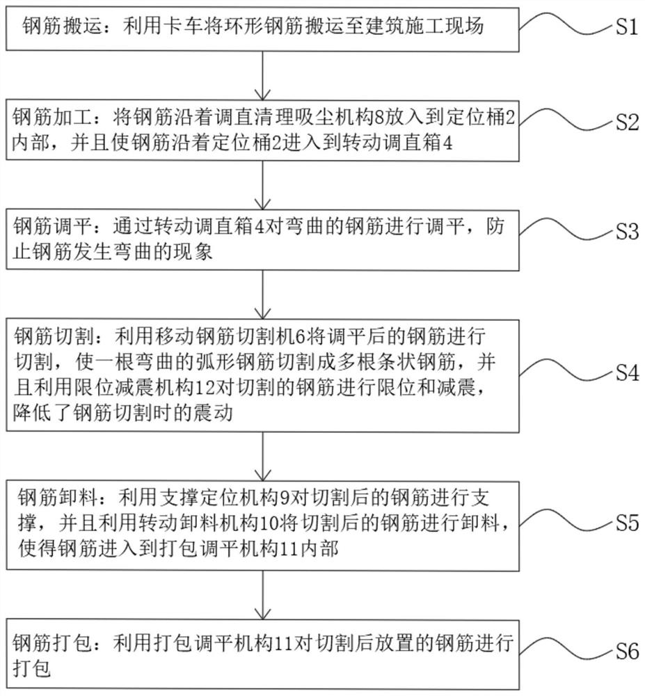
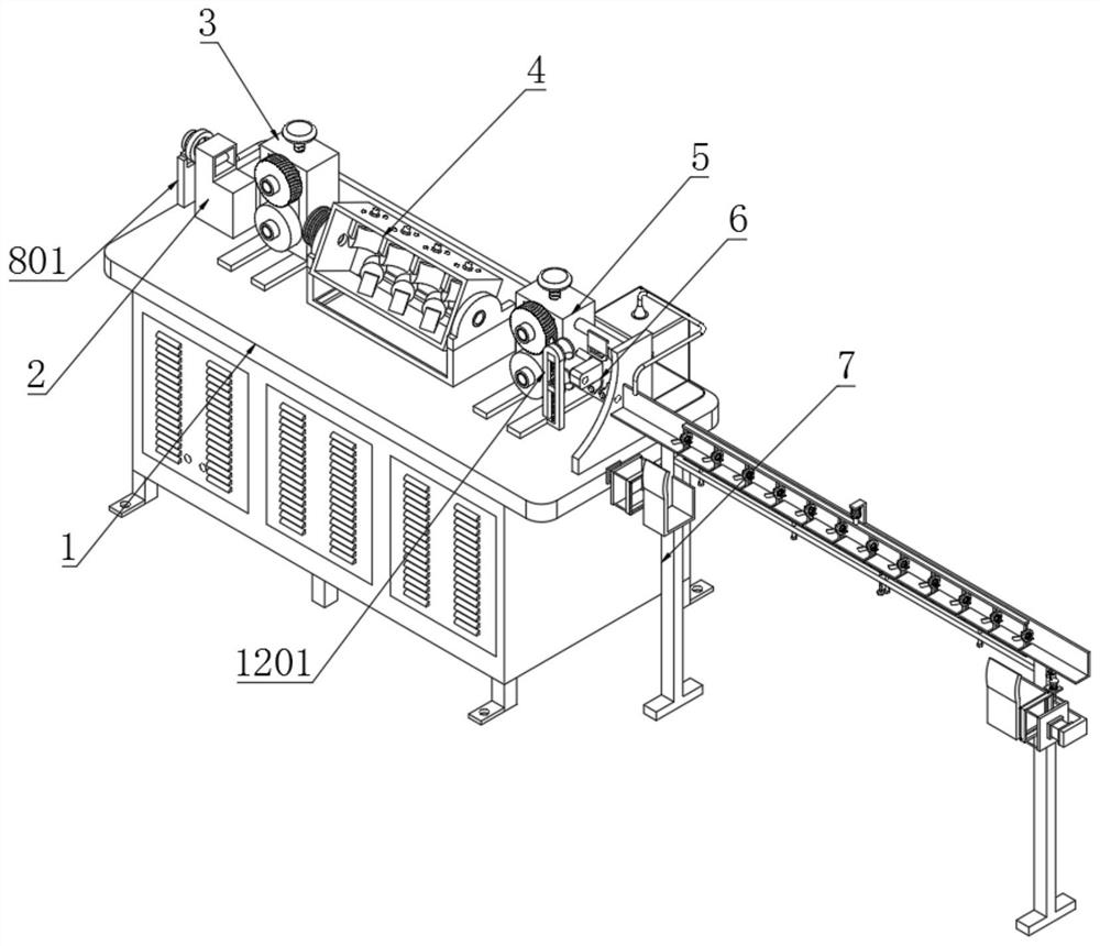
[0066] Example: such as figure 1 As shown, the present invention provides a technical solution, S1; steel bar handling: utilize trucks to transport ring-shaped steel bars to the construction site;

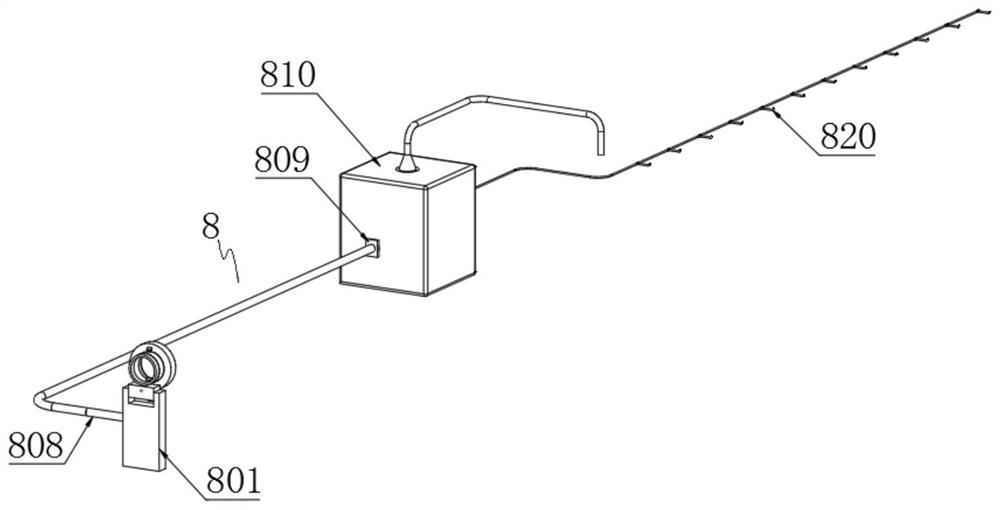
[0067] S2: steel bar processing: put the steel bar into the positioning bucket 2 along the straightening and cleaning dust suction mechanism 8, and make the steel bar enter the rotating straightening box 4 along the positioning bucket 2;

[0068] S3; steel bar leveling: leveling the bent steel bar by rotating the straightening box 4 to prevent the steel bar from bending;

[0069] S4; steel bar cutting: Utilize mobile steel bar cutting machine 6 to cut the leveled steel bar, so that a curved arc steel bar is cut into a plurality of bar-shaped steel bars, and utilize the limit shock absorbing mechanism 12 to limit the cut steel bar Position and shock absorption, reducing the vibration when cutting steel bars;

[0070] S5: Steel bar unloading: use the support positioning mechanism 9...


PUM


Abstract

The invention discloses an efficient construction mode based on a construction site. The efficient construction mode comprises the following steps of S1, reinforcing steel bar carrying, specifically,carrying annular reinforcing steel bars to the building construction site by utilizing a truck; and S2, reinforcing steel bar machining, specifically, putting the reinforcing steel bars into a positioning barrel along a rotating circular ring, and enabling the reinforcing steel bars to enter a rotating straightening box along the positioning barrel. By means of a straightening, cleaning and dust collecting mechanism, the reinforcing steel bars entering a reinforcing steel bar straightening machine can be preliminarily straightened conveniently, meanwhile rust on the surfaces of the reinforcingsteel bars entering the reinforcing steel bar straightening machine can be removed, the problem that the rust remains on the surfaces of the reinforcing steel bars in the prior art is solved, meanwhile, the problem that the removed rust is inconvenient to collect in the prior art is solved, airflow during rust collection can rapidly cool the straightened reinforcing steel bars, heat on the surfaces of the reinforcing steel bars is reduced, therefore the reinforcing steel bars can be conveniently cut, the cutting difficulty of the reinforcing steel bars is reduced, and the surface cleanness ofthe reinforcing steel bars is ensured.

Description

technical field [0001] The invention relates to the technical field of construction processing, in particular to an efficient construction method based on a construction site. Background technique [0002] Steel bar processing machinery is to process coiled steel bars and straight steel bars into length dimensions, curved shapes or installation components required for steel bar installation and construction, mainly including strengthening, straightening, bending hoops, cutting, bending, component forming and steel bar continuation Reinforcement components include reinforcement cages, reinforcement trusses (such as triangular beams, wall panels, columns, girders, etc.), reinforcement mesh, etc.; [0003] However, when the existing steel bars are processed, there is no dust-absorbing and cooling device after the steel bars are derusted, resulting in residual heat on the surface of the steel bars after straightening, and dust remaining on the surface of the steel bars, which is...

Claims


Application Information

Patent Timeline
Patent Type & Authority Applications(China)
IPC IPC(8): B21F11/00B21F1/02B08B15/04B08B1/00F16F15/067B65B27/10
CPCB21F11/00B21F1/026B08B15/04F16F15/067B65B27/10B08B1/12
Inventor 朱善由
Owner 朱善由
Why Eureka
Try Eureka