
Surface smoothness treatment method for clutch pressure plate

A technology with smooth surface and processing method, which is applied in the field of auto parts processing, can solve the problems of low efficiency, difficult to remove rough spots, uneven processing, etc., and achieve high efficiency, improve processing uniformity, and good processing effect

Inactive Publication Date: 2021-02-05
WUHU DAJIE CLUTCH
View PDF8 Cites 0 Cited by
  • Summary
  • Abstract
  • Description
  • Claims
  • Application Information

AI Technical Summary

Problems solved by technology

[0003] The existing grinding equipment generally only uses the motor to drive the grinding disc to rotate to polish the clutch pressure plate, the treatment is not uniform enough, it is difficult to remove some stubborn rough spots, and a large amount of debris is likely to be generated during the treatment process, which affects the polishing effect. At the same time, It is cumbersome and inefficient to manually remove after processing. Therefore, the present invention proposes a method for processing the surface smoothness of the clutch pressure plate to solve the problems existing in the prior art.

Method used


Image

  • Surface smoothness treatment method for clutch pressure plate
  • Surface smoothness treatment method for clutch pressure plate
  • Surface smoothness treatment method for clutch pressure plate

Examples


Embodiment Construction

[0020] In order to deepen the understanding of the present invention, the present invention will be further described below in conjunction with the examples, which are only used to explain the present invention, and do not constitute a limitation to the protection scope of the present invention.

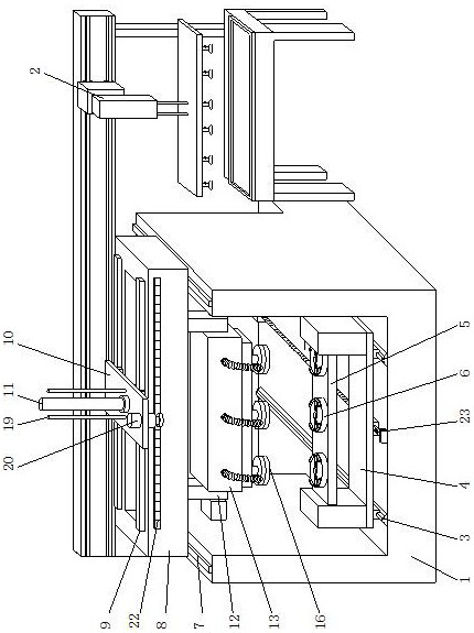
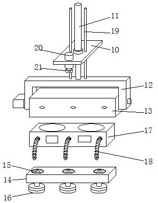
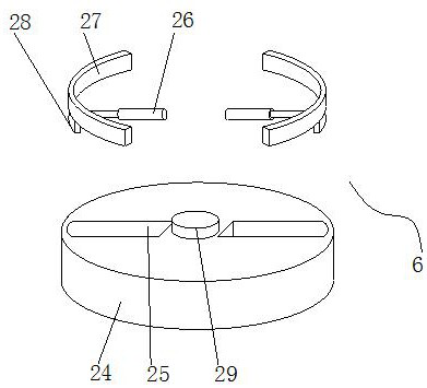
[0021] according to figure 1 , 2 , 3, 4, and 5, the present embodiment proposes a method for treating the surface smoothness of the clutch pressure plate, including a processing bin 1 and a storage assembly 2, the rear of the processing bin 1 is provided with a storage assembly 2, and the processing The bottom inside the warehouse 1 is provided with a first guide rail 3, and a U-shaped slide plate 4 is movably installed on the first guide rail 3, and a support plate 5 is provided on the U-shaped slide plate 4, and a clamping assembly is rotatably installed on the support plate 5 6. Both sides of the top of the processing chamber 1 are provided with a first electromagnetic slide rail...


PUM


Abstract

The invention provides a surface smoothness treatment method for a clutch pressure plate. The surface smoothness treatment method comprises a treatment bin and a storage assembly, wherein the storageassembly is arranged behind the treatment bin; a first guide rail is arranged on the bottom inside the treatment bin; a U-shaped slide plate is movably mounted on the first guide rail; a supporting plate is arranged on the U-shaped slide plate; a clamping assembly is rotatably mounted on the supporting plate; first electromagnetic slide rails are arranged at the two sides of the top of the treatment bin; and slide bins are movably mounted on the first electromagnetic slide rails. According to the surface smoothness treatment method provided by the invention, the clamping assembly is used for clamping and fixing the clutch pressure plate, a first pneumatic cylinder is utilized to put down a U-shaped frame, and a polishing motor drives a polishing disc to rotate for performing smoothness treatment on the surface of the clutch pressure plate clamped on the clamping assembly; a rotary bin rotates to change the angle of the polishing disc to perform multi-angle polishing, so that stubborn rough spots on the surface of the clutch pressure plate are conveniently removed; and the rotation function of the clamping assembly is utilized to drive the clutch pressure plate to rotate to be matched with polishing, so that processing uniformity further can be improved.

Description

technical field [0001] The invention relates to the technical field of automobile parts processing, in particular to a method for treating the surface smoothness of a clutch pressure plate. Background technique [0002] The clutch pressure plate is an important structure on the clutch, and its function plays an important role in the driving safety of the car. The clutch pressure plate is one of the most important parts in the clutch assembly. It transmits and cuts off the engine through the linkage mechanism according to the driver's wishes. The power transmission, and cooperate with the clutch plate, make the vehicle start smoothly, shift smoothly and prevent the engine from overloading, which is of great help in the driving of the car. When the clutch pressure plate is produced, in order to ensure the performance of the clutch pressure plate It is often necessary to perform smoothness treatment on the surface of the clutch pressure plate, that is, polishing; [0003] The ...

Claims


Application Information

Patent Timeline
Patent Type & Authority Applications(China)
IPC IPC(8): B24B1/00B24B29/02B24B41/06B24B55/12
CPCB24B1/00B24B29/02B24B41/06B24B55/12
Inventor 吴安琦董祥辉俞明李德邵毕承琪戴晓明
Owner WUHU DAJIE CLUTCH
Learn More