Automatic glass edging production line

A glass edging and production line technology, which is applied to machine tools, grinders, and workpiece supports for grinding workpiece edges, can solve problems such as low processing efficiency, improve processing quality, increase friction, and facilitate transportation. Effect

Inactive Publication Date: 2021-02-05
CHONGQING CONGBO ENERGY SAVING GLASS CO LTD
View PDF5 Cites 0 Cited by
  • Summary
  • Abstract
  • Description
  • Claims
  • Application Information

AI Technical Summary

Problems solved by technology

[0003] When the existing glass edging machine grinds the sides of the glass, it usually grinds one side or two sides. In the actual glass grinding work, it is necessary to grind the four sides of the glass. For the four sides, the current method is: The glass is ground on both sides, and then the operator takes the glass from the exit position of the glass edging machine to the entrance position and rotates it to process the other two sides of the glass. The processing efficiency is low.

Method used


Image

  • Automatic glass edging production line
  • Automatic glass edging production line
  • Automatic glass edging production line

Examples


Embodiment 1

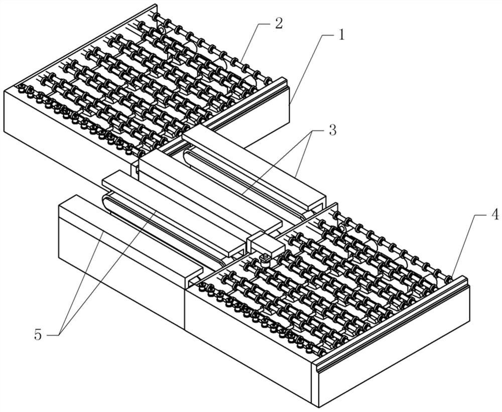
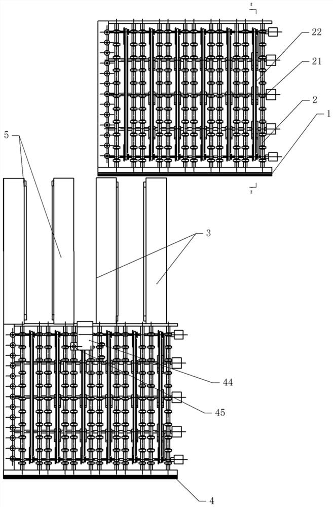
[0037] Basic as attached figure 1 And attached figure 2 Shown: an automatic glass edging production line, including a frame on which a first transmission mechanism 1 and a second transmission mechanism 4 are installed. In this embodiment, the first transmission mechanism 1 and the second transmission mechanism 4 both include The roller feeding mechanism and several belt feeding mechanisms are uniformly distributed along the length direction of the frame, and the roller feeding mechanism and the belt feeding mechanism are arranged alternately. The roller feeding mechanism conveys the glass horizontally, and the belt feeding mechanism conveys the glass longitudinally.

[0038]The end of the conveying direction of the belt feeding mechanism of the first conveying mechanism 1 is provided with a first bilateral edging device 3, and the end of the conveying direction of the belt feeding mechanism of the second conveying mechanism 4 is provided with a second bilateral edging device...

Embodiment 2

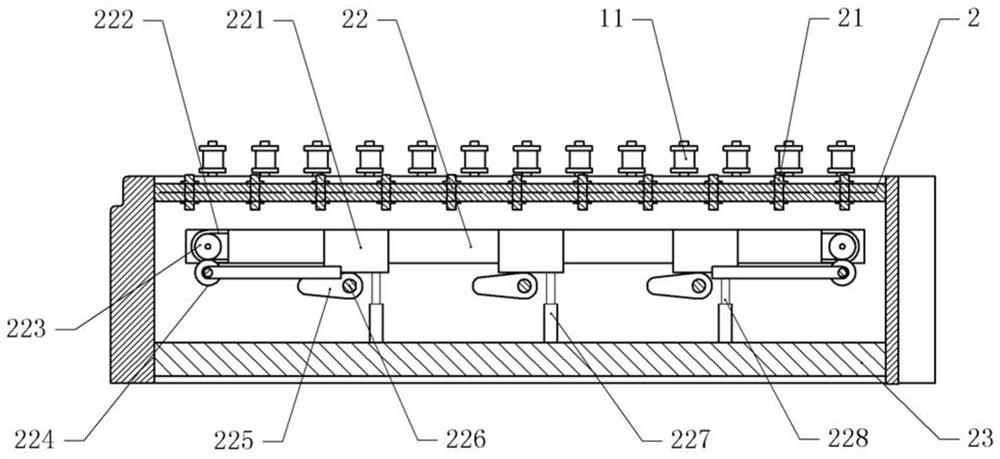
[0045] The difference between embodiment two and embodiment one is that, as attached Figure 6 And attached Figure 7 As shown, a cavity 231 is opened in the mounting plate 23, and a pressure plate 232 is vertically slidably connected to the cavity 231, and the pressure plate 232 is fixedly connected to the inner shaft 228 by bolts. Valve 25. An air chamber 12 is arranged below the guide roller 11 on the frame, and the air chamber 12 communicates with the air outlet check valve 25 through a pipeline.

[0046] The guide roller 11 includes a support shaft that is rotatably connected with the frame. There is an air channel 13 communicating with the air chamber 12 in the support shaft. There is a communication hole 14 on the support shaft. A guide cylinder is sleeved on the support shaft, and the guide cylinder and the support An exhaust cavity 15 is formed between the shafts, and an air hole 16 is formed on the side wall of the guide cylinder, and the air hole 16 communicates w...


PUM


Abstract

The invention relates to the technical field of glass edging, and discloses an automatic glass edging production line. The automatic glass edging production line comprises a rack, wherein a first conveying mechanism and a second conveying mechanism are arranged on the rack, each of the first conveying mechanism and the second conveying mechanism comprises a roller conveying mechanism and a plurality of belt conveying mechanisms, and the belt conveying mechanisms and the roller conveying mechanisms are arranged in a staggered mode; first bilateral edging devices are arranged at the tail ends ofthe belt conveying mechanisms in the conveying direction, the second conveying mechanism is located at the tail ends of the first bilateral edging devices in the conveying direction, and a second bilateral edging device is arranged at the tail end of the second conveying mechanism in the conveying direction; driving mechanisms for driving the roller conveying mechanisms are arranged below the roller conveying mechanisms, and lifting mechanisms for lifting the belt conveying mechanisms are arranged below the belt conveying mechanisms; and a steering mechanism is arranged on the side, close tothe first bilateral edging device, of the second conveying mechanism. The automatic glass edging production line has the advantages of being simple in structure and capable of edging glass efficiently.

Description

technical field [0001] The invention relates to the technical field of glass edging, and specifically discloses an automatic glass edging production line. Background technique [0002] Glass edging machine is one of the earliest and most widely used mechanical equipment in glass deep processing equipment. Its main function is to smooth the glass and make some special shapes. [0003] When the existing glass edging machine grinds the sides of the glass, it usually grinds one side or two sides. In the actual glass grinding work, it is necessary to grind the four sides of the glass. For the four sides, the current method is: The glass is ground on both sides, and then the operator takes the glass from the exit position of the glass edging machine to the entrance position and rotates it to process the other two sides of the glass, and the processing efficiency is low. Contents of the invention [0004] The invention intends to provide an automatic glass edging production line...

Claims


Application Information

Patent Timeline
IPC IPC(8): B24B9/10B24B7/06B24B7/17B24B27/00B24B41/06B24B47/20B24B55/06
CPCB24B7/06B24B7/17B24B9/102B24B27/0023B24B27/0069B24B41/06B24B47/20B24B55/06
Inventor 王洪
Owner CHONGQING CONGBO ENERGY SAVING GLASS CO LTD
Why Eureka
Try Eureka