Photographic lamp shade machining integrated device

A technology for photographic lamps and lampshades, applied in grinding drive devices, metal processing equipment, grinding/polishing safety devices, etc., can solve problems such as incomplete internal and external cleaning, affect processing quality, and prolong grinding time, so as to ensure water recovery The effect of improving quality, avoiding unstable fixation, and reducing processing time

Active Publication Date: 2021-02-05
苏州市博通照明电器有限公司
View PDF5 Cites 1 Cited by
  • Summary
  • Abstract
  • Description
  • Claims
  • Application Information

AI Technical Summary

Problems solved by technology

[0004] The object of the present invention is to provide an integrated device for processing photographic lamp shades to solve the problem that the outer and inner sides of the existing photographic lamp shades proposed in the background technology mentioned above need to be polished separately, which will prolong the entire grinding time and affect The overall processing efficiency, when cleaning, takes a long time to clean, and the internal and external cleaning is not thorough, which affects the quality of post-processing. At the same time, the water after cleaning is not recycled and reused, resulting in the waste of water resources.

Method used


Image

  • Photographic lamp shade machining integrated device
  • Photographic lamp shade machining integrated device
  • Photographic lamp shade machining integrated device

Examples


Embodiment Construction

[0034] The following will clearly and completely describe the technical solutions in the embodiments of the present invention with reference to the accompanying drawings in the embodiments of the present invention. Obviously, the described embodiments are only some, not all, embodiments of the present invention. Based on the embodiments of the present invention, all other embodiments obtained by persons of ordinary skill in the art without making creative efforts belong to the protection scope of the present invention.

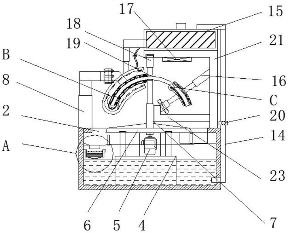
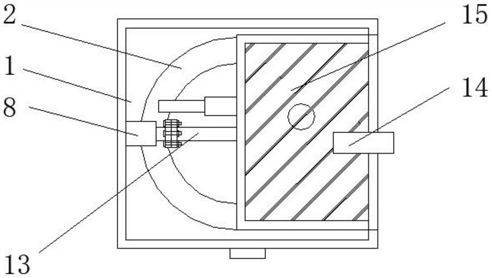
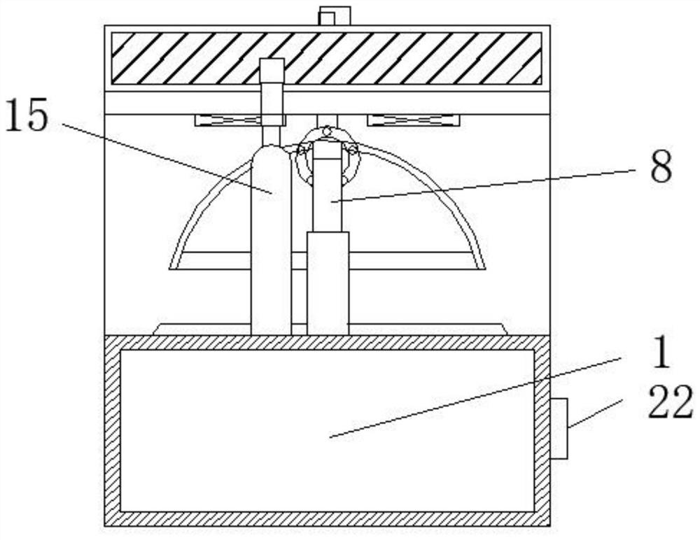
[0035] see Figure 1-9 , the present invention provides a technical solution: an integrated device for processing photographic lamp shades, such as figure 1 , figure 2 and Figure 7 As shown, the base 1 is penetrated with a water inlet 2, and the water inlet 2 is located on the upper side of the filter recovery assembly 3, while the filter recovery assembly 3 is located inside the base 1, and a control box 22 is fixed on the front side of the base 1. The fi...


PUM


Abstract

The invention discloses a photographic lamp shade machining integrated device. The photographic lamp shade machining integrated device comprises a base, a first U-shaped fixing plate, a second electric telescopic rod, a first water conveying pipe and an auxiliary clamping assembly, wherein a water inlet is formed in the base in a penetrating mode, a stepping motor is fixed to the upper side of thefirst U-shaped fixing plate, the output end of the stepping motor is rotationally connected with a first supporting plate, anti-skid fixing plates are fixed to one ends of a first electric telescopicrod and a fifth electric telescopic rod correspondingly, a second supporting plate is fixed to the upper side of the second electric telescopic rod, a grinding assembly is fixed to one end of a connecting rod, one end of the first water conveying pipe communicates with a cleaning assembly, and the auxiliary clamping assembly is used for carrying out auxiliary clamping on a photographic lamp shade. The photographic lamp shade machining integrated device is provided with the grinding assembly, grinding plates are fixed to the upper inner wall and the lower inner wall of a second U-shaped lightplate in the grinding assembly, and therefore the outer wall and the inner wall of the photographic lamp shade can be ground at the same time.

Description

technical field [0001] The invention relates to the technical field of lamp shades for photographic lamps, in particular to an integrated device for processing lamp shades for photographic lamps. Background technique [0002] Lampshade, a cover set on the periphery of the flame or on the bulb to concentrate light or prevent wind and rain. The lampshade is not only used to cover the lamp to gather the light, but also to prevent electric shock and protect the eyes. Common lampshade materials generally include fabric, pvc, kraft paper and so on. For new LED lamps, the lampshade is generally metal. [0003] When the existing photographic lamp shade is processed and polished, the outer side and the inner side need to be polished separately, which will prolong the entire polishing time and affect the overall processing efficiency. When cleaning, the cleaning time is longer, and the internal and external cleaning is not thorough, which affects the post-processing quality. The was...

Claims


Application Information

Patent Timeline
Patent Type & Authority Applications(China)
IPC IPC(8): B24B19/00B24B41/06B24B55/06B24B41/02B24B47/04B01D29/01B01D29/27B01D29/58
CPCB24B19/00B24B41/06B24B55/06B24B41/02B24B47/04B01D29/01B01D29/27B01D29/58Y02P70/10
Inventor 叶剑清
Owner 苏州市博通照明电器有限公司
Why Eureka
Try Eureka