
A combined ocean platform

An ocean platform and combined technology, applied in ocean energy power generation, machines/engines, mechanical equipment, etc., can solve problems such as low cost performance, difficult control of vibration reduction effect, and insufficient use of wave renewable resources

Inactive Publication Date: 2021-10-29
HOHAI UNIV +1
View PDF0 Cites 0 Cited by
  • Summary
  • Abstract
  • Description
  • Claims
  • Application Information

AI Technical Summary

Problems solved by technology

Among them, the floating box type offshore platform is the preferred type of combined module, but due to the small draft of this type of structure, the movement response is significant under the action of waves, and the stability problem limits the large-scale engineering application
The existing vibration reduction measures for buoyant tank-type offshore platforms are mainly to increase platform stiffness, install equal-length rectangular buoyant tank vibration-reducing devices on the side of the platform, and use tuned liquid dampers, but the cost of increasing stiffness is relatively high, and the cost performance is not high; The equal-length rectangular pontoon damping device increases the reflection area of ​​waves on the frontal surface, and the superposition of wave reflections will form a larger wave force; the performance of the tuned liquid damper is affected by many aspects such as the natural frequency of the platform structure and the design parameters of the damper itself. The vibration reduction effect is difficult to control, and most of the current measures only consider how to reduce the impact of waves, and do not make full use of wave energy, a renewable resource

Method used


Image

  • A combined ocean platform
  • A combined ocean platform
  • A combined ocean platform

Examples


Embodiment Construction

[0034] The present invention will be further described below in conjunction with the accompanying drawings. The following examples are only used to illustrate the technical solution of the present invention more clearly, but not to limit the protection scope of the present invention.

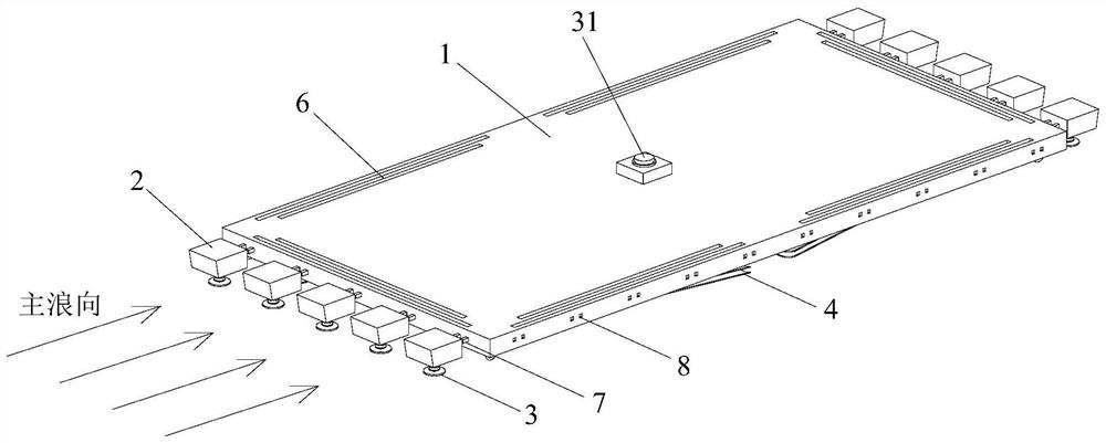
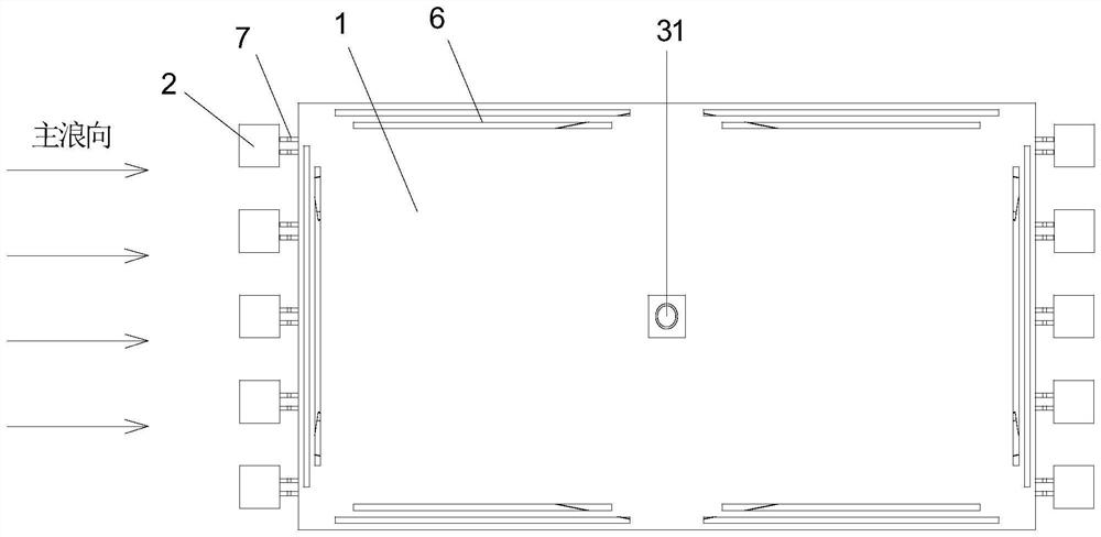
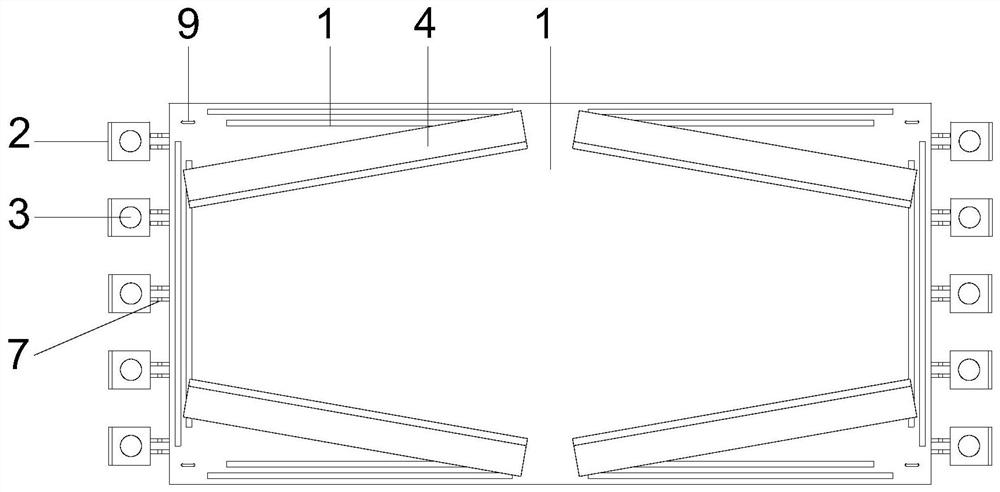
[0035] The invention relates to a combined offshore platform, which includes a floating platform 1 that can be connected and combined, and also includes a T-shaped anti-wave tooth 2 that can simultaneously realize wave dissipation and energy supply by wave energy, and a double anti-wave gear for restraining platform movement. Layer arc wave-proof partition 4.

[0036] like figure 1 , 2 As shown, the side length of the floating platform 1 is 200m×100m, and five anti-wave teeth 2 are connected to the edge of the floating platform 1 facing waves (the short side of the platform in the example) through the connector 7, and the distance between each anti-wave tooth 2 20m, a single floating platform...


PUM


Abstract

The invention discloses a combined ocean platform, which comprises a floating platform. The facing side of the floating platform is provided with a plurality of anti-wave teeth for wave dissipation to form a toothed structure; the bottom of the floating platform is provided with a Anti-wave bulkheads used to restrain the movement of floating platforms. The invention reduces the peak value of the total wave force by arranging a plurality of anti-wave teeth on the wave-facing side of the floating platform, and arranges an anti-wave partition at the bottom of the floating platform to achieve the effect of wave dissipation, thereby reducing the movement of the floating platform response.

Description

technical field [0001] The invention relates to a combined ocean platform, which belongs to the technical field of ocean engineering. Background technique [0002] In the 21st century, as the era of marine economy with global consensus, the development of marine resources has always attracted people's attention. Ocean platforms provide the basis for production and living equipment for offshore operations, so the establishment of ocean platforms is of great significance to the utilization of ocean space. At this stage, in order to effectively exploit marine resources and utilize marine space, large-scale offshore platforms have become a trend. However, the large-scale offshore platform also brings many difficulties, such as difficulties in production and transportation, and severe environmental loads. Especially under the action of waves, the offshore platform will undergo translational, swaying, and ups and downs. If the movement range is large, it will greatly affect the ...

Claims


Application Information

Patent Timeline
Patent Type & Authority Patents(China)
IPC IPC(8): B63B35/44B63B39/03B63B39/10F03B13/18
CPCB63B35/44B63B39/03B63B39/10F03B13/1845F05B2220/706Y02E10/30
Inventor 黄挺李俊龙何良德严士常王荣陶然
Owner HOHAI UNIV
Learn More