
Conveying device

A conveying device and straight-line conveying technology, which is applied in the direction of conveyors, mechanical conveyors, conveyor objects, etc., and can solve problems such as low conveying efficiency

Active Publication Date: 2021-02-05
北京可锐特科技有限公司
View PDF10 Cites 3 Cited by
  • Summary
  • Abstract
  • Description
  • Claims
  • Application Information

AI Technical Summary

Problems solved by technology

[0003] Usually, in order to better allow the pallet to be recycled, two parallel conveyor belts with opposite directions are set up. One conveyor belt is the direction to transport the workpiece, and the other is the direction to transport the pallet back. However, these two parallel conveyor belts When the belt is turned in the middle and rotated in situ, it still needs to be manually operated, resulting in low conveying efficiency

Method used


Image

  • Conveying device
  • Conveying device
  • Conveying device

Examples


Embodiment Construction

[0045] The technical solutions in the embodiments of the present invention will be clearly and completely described below in conjunction with the accompanying drawings in the embodiments of the present invention. Obviously, the described embodiments are only some, not all, embodiments of the present invention. Based on the embodiments of the present invention, all other embodiments obtained by persons of ordinary skill in the art without creative efforts fall within the protection scope of the present invention.

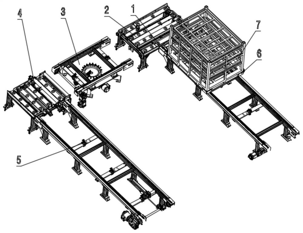
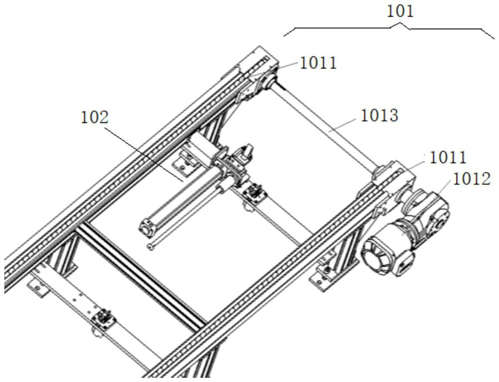
[0046] According to an embodiment of the present invention, such as figure 1 As shown, a conveying device is provided, including: a first linear conveying mechanism 1, which conveys a pallet 6 loaded with a workpiece 7 in a pushing manner; a first 90° turning conveying mechanism 2, which is arranged on the first linear conveying mechanism 1, the first 90° turning conveying mechanism 2 receives the pallet 6 pushed by the first linear conveying mechanism 1, and conveys...


PUM


Abstract

The invention discloses a conveying device. Automatic rotation of a tray can be completed through a first 90-degree turning conveying mechanism and a second 90-degree turning conveying mechanism, in-situ horizontal rotation of a workpiece on the tray can be achieved through a 180-degree rotating conveying mechanism, and the workpiece can be conveniently grabbed by a grabbing tool. Therefore, the conveying device requires no manual operation, the conveying efficiency is improved, the distance between a first linear conveying mechanism and a second linear conveying mechanism is small, that is, the butt joint space between the conveying mechanisms is small, the occupied space of the conveying device is reduced, and the applicability and the conveying stability of the conveying device are improved.

Description

technical field [0001] The invention relates to the technical field of transportation, in particular to a transportation device. Background technique [0002] In the process of transferring workpieces in the automatic transportation line, the workpieces are usually placed on pallets for transportation, and according to the needs of functions, loop devices need to be added at some transportation nodes to complete the 90-degree turning of the workpieces, and then put the pallets in place Rotating 180 degrees is convenient for workpiece grabbing. After the workpiece is grabbed, the pallet rotates back 180 degrees and continues to transport to the next station, and finally rotates 90 degrees to continue transporting, so that the pallet can be reused. [0003] Usually, in order to better allow the pallet to be recycled, two parallel conveyor belts with opposite directions are set up. One conveyor belt is the direction to transport the workpiece, and the other is the direction to ...

Claims


Application Information

Patent Timeline
Patent Type & Authority Applications(China)
IPC IPC(8): B65G37/00B65G47/53B65G47/244B65G15/22B65G25/08B65G47/82
CPCB65G37/00B65G47/53B65G47/244B65G15/22B65G25/08B65G47/82B65G2201/0258Y02P70/10
Inventor 王奇志刘海涛
Owner 北京可锐特科技有限公司
Learn More