
A textile roller with automatic lubricity detection and adjustment and its use method

An automatic detection and textile roller technology, applied in the direction of lubricating parts, engine lubrication, engine components, etc., can solve the problems of time-consuming fixed installation, inconvenient operation, and constant fixed installation, etc., to achieve simple and convenient fixing, easy replacement and disassembly Effect

Active Publication Date: 2021-08-03
苏州市卓群纺织科技有限公司
View PDF5 Cites 0 Cited by
  • Summary
  • Abstract
  • Description
  • Claims
  • Application Information

AI Technical Summary

Problems solved by technology

[0004] 1. After the existing textile roller is installed, the user needs to use multiple fixing parts to fix the work. The fixed installation takes a long time and is laborious at the same time, resulting in relatively unchanged fixed installation and inconvenient disassembly and replacement of the textile roller;
[0005] 2. The height of the existing textile rollers cannot be adjusted again after they are installed and fixed. As a result, if the product in the early stage of winding is loose or too tight, it cannot be adjusted and the winding work needs to be re-wound, resulting in inconvenient use;
[0006] 3. The existing textile rollers need lubricating oil to lubricate the rotating position during use to reduce friction, thereby reducing wear and improving the service life of the device. However, the existing lubricating oil is manually added, and manual detection is required. It needs to be added, and the machine needs to be turned off when adding, so as to facilitate the adding work, the operation is inconvenient, and at the same time, the production efficiency will be affected when the machine is stopped, so a device is urgently needed to solve the above problems

Method used


Image

  • A textile roller with automatic lubricity detection and adjustment and its use method
  • A textile roller with automatic lubricity detection and adjustment and its use method
  • A textile roller with automatic lubricity detection and adjustment and its use method

Examples


Embodiment Construction

[0034] The following will clearly and completely describe the technical solutions in the embodiments of the present invention with reference to the accompanying drawings in the embodiments of the present invention. Obviously, the described embodiments are only some, not all, embodiments of the present invention. Based on the embodiments of the present invention, all other embodiments obtained by persons of ordinary skill in the art without making creative efforts belong to the protection scope of the present invention.

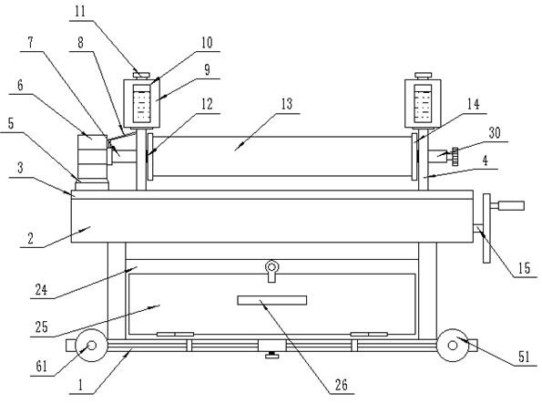
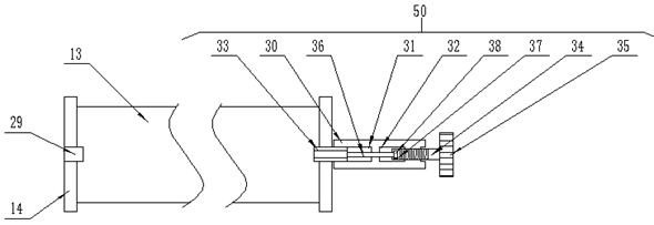
[0035] see Figure 1-8 , the present invention provides a technical solution: a textile roller with automatic lubricity detection and adjustment, including a support frame 1, a horizontal plate 2 and a textile roller main body 13, and the positions on both sides of the front end of the support frame 1 are movable and interspersed with wheel shafts 61, The front end position of the wheel shaft 61 is fixedly installed with a moving wheel 51, the moving wheel 51 ...


PUM


Abstract

The invention discloses a textile roller with automatic detection and adjustment of lubricity and a method for using the same. It comprises a support frame, a horizontal plate and a main body of the textile roller. Wheel shafts are movable and interspersed on both sides of the front end of the support frame, and the front end of the wheel shaft is fixed in position. A moving wheel is installed, a limit mechanism is arranged at the front end of the support frame, and a storage mechanism is arranged at the center of the upper end of the support frame. In the present invention, the raw material is wound on the outer end of the main body of the textile roller, and then the user rotates the turntable through the rocker, so that the turntable drives the movable shaft to rotate, and the movable ring moves to the left through the screw thread, thereby squeezing the first connecting rod to the left, so that The movable block moves upward to lift the support plate, so as to facilitate the lifting of the support plate height. When the height of the support plate needs to be lowered again, the user can turn the turntable in the opposite direction, and the tension of the winding material can be adjusted by moving the support plate up and down. , so that the raw material is in a suitable tension when winding.

Description

technical field [0001] The invention relates to the field of textile equipment, in particular to a textile roller with automatic lubricity detection and adjustment and a use method thereof. Background technique [0002] The original meaning of textile is taken from the general term of spinning and weaving, but with the continuous development and improvement of the textile knowledge system and subject system, especially after the emergence of non-woven textile materials and three-dimensional composite weaving technologies, it is not only the traditional hand spinning And weaving, including non-woven fabric technology, modern three-dimensional weaving technology, modern electrostatic nano-netting technology and other textiles for clothing, industry and decoration; ancient Chinese textile and printing and dyeing technology has a very long history, as early as In the primitive society, in order to adapt to climate change, the ancients knew how to use local materials, use natural...

Claims


Application Information

Patent Timeline
Patent Type & Authority Patents(China)
IPC IPC(8): B65H18/10B65H23/195B65H19/30F16C33/66F16N7/02F16N21/00
CPCB65H18/10B65H19/30B65H23/195B65H2515/31F16C33/6659F16N7/02F16N21/00F16N2210/14
Inventor 黄静
Owner 苏州市卓群纺织科技有限公司
Learn More