
Mechanical device for removing wound yarn from warp beam of textile machinery

A mechanical device and mechanical warp technology, applied in the field of textile fabrics, can solve the problems of troublesome cleaning, increasing the workload of workers, and winding the yarn on the warp beam.

Pending Publication Date: 2021-02-05
厦门瓯耶烨纺织机械有限公司
View PDF0 Cites 0 Cited by
  • Summary
  • Abstract
  • Description
  • Claims
  • Application Information

AI Technical Summary

Problems solved by technology

[0004] Aiming at the deficiencies of the prior art, the present invention provides a mechanical device for removing windings from a warp beam of a textile machine, which has the advantages of performing secant processing on the yarn wound on the warp beam and collecting the cut yarn, and solves the problem of During the process of the high-speed rotation of the machine on the production line, the yarn will be entangled on the warp beam, and the entangled yarn will become tighter and tighter with the rotation of the machine, and it will be very troublesome to clean up. The yarn wound on the shaft will increase the workload of workers and reduce the production efficiency of the assembly line

Method used


Image

  • Mechanical device for removing wound yarn from warp beam of textile machinery
  • Mechanical device for removing wound yarn from warp beam of textile machinery
  • Mechanical device for removing wound yarn from warp beam of textile machinery

Examples


Embodiment Construction

[0022] The following will clearly and completely describe the technical solutions in the embodiments of the present invention with reference to the accompanying drawings in the embodiments of the present invention. Obviously, the described embodiments are only some, not all, embodiments of the present invention. Based on the embodiments of the present invention, all other embodiments obtained by persons of ordinary skill in the art without making creative efforts belong to the protection scope of the present invention.

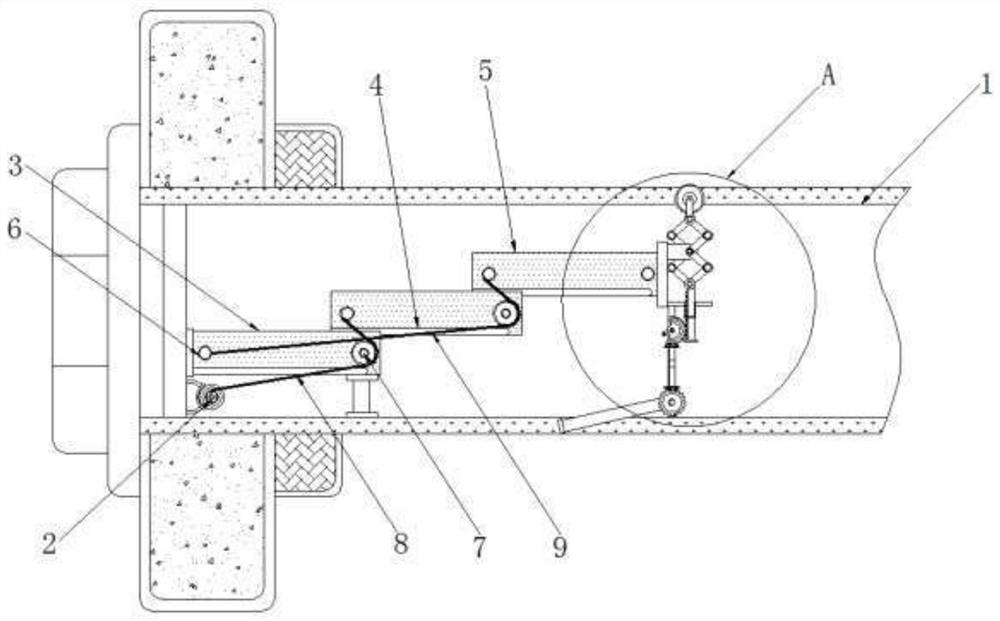
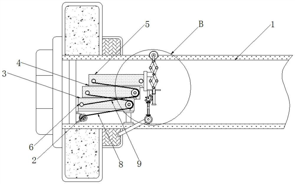
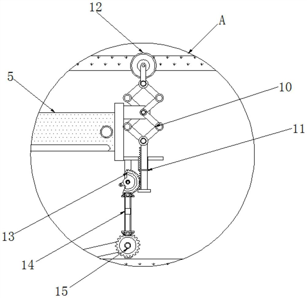
[0023] see Figure 1-4 , a mechanical device for removing a coiled thread from a warp beam of a textile machine, comprising a warp beam 1, a wire reel 2 is installed movable inside the warp beam 1, a fixed rod-3 is fixedly installed on the top of the wire reel 2, and a fixed rod-3 Fixed rod two 4 is installed movable above the fixed rod two 4, fixed rod three 5 is installed movable above the fixed rod two 4, fixed rod one 3, fixed rod two 4, fixed rod three 5 ...


PUM


Abstract

The invention relates to the technical field of textile fabrics, and discloses a mechanical device for removing wound yarn from a warp beam of textile machinery. A third fixing rod and a second fixingrod are driven to slide towards the left side through a first connecting rope and a second connecting rope, so that a cutter installed at the right end of the third fixing rod is pulled to move towards the left side, when yarn wound on the warp beam is cut, and the situations that the yarn wound on the warp beam needs to be manually cleaned by workers, the working efficiency is reduced and the workload is reduced are avoided. A sector gear rotates to push a toothed bar to move upwards, a folding rod is extended, the cutter is pushed out of the warp beam from the inner side of the warp beam, the sector gear drives a double-ratchet rod, the double-ratchet rod drives a first gear to rotate, a wiring rod is installed on the outer side of the first gear, and the wiring rod is driven by the first gear to rotate to the outer side of the warp beam from the inner side of the warp beam, so that tightly-wound yarn is mechanically cut, and the cut yarn falls onto the wiring rod.

Description

technical field [0001] The invention relates to the technical field of textile fabrics, in particular to a mechanical device for removing winding threads from a warp beam of a textile machine. Background technique [0002] In the textile industry, mechanized production has replaced the traditional labor force. The textile industry produces fast and the machine runs extremely fast. When the yarn on the production line is rotating at a high speed, the yarn will be wound on the warp beam, and the winding The yarn will become tighter and tighter with the rotation of the machine, and cleaning will be very troublesome. Cleaning up the yarn wound on the warp beam will increase the workload of the workers and reduce the production efficiency on the assembly line. Contents of the invention [0003] (1) Solved technical problems [0004] Aiming at the deficiencies of the prior art, the present invention provides a mechanical device for removing windings from a warp beam of a textil...

Claims


Application Information

Patent Timeline
Patent Type & Authority Applications(China)
IPC IPC(8): B65H73/00B26D7/00B26D5/08B26D5/02B26D1/147B26D1/04
CPCB26D1/04B26D1/147B26D5/02B26D5/08B26D7/0006B65H73/00B65H2701/174
Inventor 王世扬
Owner 厦门瓯耶烨纺织机械有限公司
Learn More