A synchronous cutting device with both ends

A technology of synchronous cutting and guiding devices, which is applied in metal processing and other directions, and can solve the problems of heavy load, low flexibility, and large labor load

Active Publication Date: 2017-04-05
北京京城智通机器人科技有限公司
View PDF9 Cites 0 Cited by
  • Summary
  • Abstract
  • Description
  • Claims
  • Application Information

AI Technical Summary

Problems solved by technology

The cutting machine is an indispensable equipment in the automatic production line of SCR catalyst. It is necessary to cut and separate the SCR catalyst. The cutting methods in the prior art are manual cutting and automatic cutting: manual cutting is too laborious and consumes a lot of manpower and material resources, and The quality of manual cutting is difficult to guarantee; automatic cutting is to place the long SCR catalyst block on the belt line for overall movement. During the movement, it is expected to carry a large load and have low flexibility. It is difficult to control the cutting length and the verticality of the end face, and both It is single-sided cutting, long working hours and low work efficiency

Method used


Image

  • A synchronous cutting device with both ends

Examples


Embodiment Construction

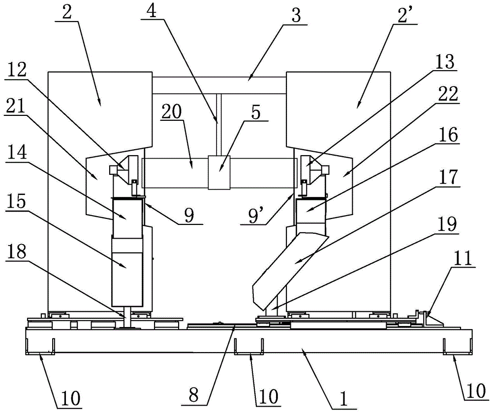
[0017] Such as figure 1 As shown, it is a front view of a synchronous cutting device at both ends of the present invention, including a base 1, a left sawing casing 2, a right sawing casing 2', a first cutting steel wire 9, a second cutting steel wire 9', a fixed Board 6, sliding board 7 and central controller. The base 1 is a flat plate structure placed along the horizontal direction, and a plurality of anti-slip pads 10 are uniformly arranged on the edge of the bottom end of the base 1 .

[0018] The left side of the top of the base 1 is vertically provided with a left sawing case 2 with a rectangular parallelepiped structure, and the left sawing case 2 is fixedly mounted on the top of the base 1 by screws, on the right side of the left sawing case 2 The middle position of wall is provided with the first groove 21 that section is trapezoidal, and the first cutting steel wire 9 is arranged vertically on the inner wall near the opening of first groove 21 inside first groove 2...


PUM


Abstract

The invention relates to a two-end synchronous cutting device, and aims at providing a catalyst cutting device which is high in working efficiency, low in cost and high in automatic degree. The two-end synchronous cutting device comprises a base, a left saw cutting shell, a right saw cutting shell and a central control unit. The fixed left saw cutting shell and the slideable right saw cutting shell are installed on the two sides of the top of the base respectively, and a first groove and a second groove are formed in the side walls of the left saw cutting shell and the right saw cutting shell respectively; and cutting steel wires are arranged in the two grooves respectively. Guide devices are arranged in front of the left saw cutting shell and the right saw cutting shell respectively, and outlets of the guide devices are located above the base. A rotating shaft is arranged between the left saw cutting shell and the right saw cutting shell, the rotating shaft is controlled through a second driving motor, and the control end of the second driving motor is connected with the control signal output end of the central control unit. The rotating shaft is connected with an electric clamping jaw through a connection rod, and the electric clamping jaw is controlled through the central control unit.

Description

technical field [0001] The invention relates to the field of a catalyst preparation device, in particular to a two-end synchronous cutting device. Background technique [0002] At present, coal, as the main energy source of developing countries, occupies a large proportion in the energy structure of each country. However, 90% of sulfur dioxide and more than 65% of hydroxide in air pollution come from coal combustion. Among them, for controlling the discharge of hydroxides, relevant staff have done a lot of research work. At present, the denitrification part of most thermal power plants in China is controlled outside the furnace, and the selective catalyst (SCR) reduction method is mostly used to reduce the pollution of hydroxides. The cutting machine is an indispensable equipment in the automatic production line of SCR catalyst. It is necessary to cut and separate the SCR catalyst. The cutting methods in the prior art are manual cutting and automatic cutting: manual cutting...

Claims


Application Information

Patent Timeline
Patent Type & Authority Patents(China)
IPC IPC(8): B26D1/553B26D7/06B26D7/18B26D7/26
Inventor 刘少立孙云权
Owner 北京京城智通机器人科技有限公司
Why Eureka
Try Eureka