
Wind driven generator with lifting device

A technology for wind turbines and lifting equipment, which is applied to wind turbines, wind turbine combinations, wind energy power generation, etc., can solve the problems of small floor space, large physical strength, insufficient internal space to install ladders, etc., so as to facilitate maintenance work. , increased friction, flexibility and practical effects

Pending Publication Date: 2021-02-05
HUANENG TONGLIAO WIND POWER CO LTD
View PDF0 Cites 0 Cited by
  • Summary
  • Abstract
  • Description
  • Claims
  • Application Information

AI Technical Summary

Problems solved by technology

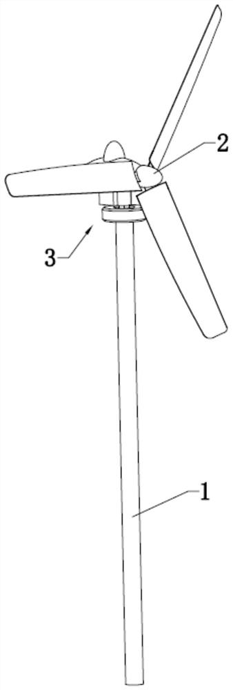
[0004] The daily maintenance of wind turbines requires operators to climb to the top by climbing ladders. Ladders are usually installed outside or inside the columns. For larger wind turbines, because the columns occupy a large area and the internal space is relatively wide, the ladders are generally installed on the There are even elevators inside the columns, but for smaller wind turbines, because the columns occupy a small area and the internal space is not enough to install ladders, they are usually installed outside. Operators need to wear safety equipment when climbing the ladders. Climbing up, due to the high position of the impeller parts, the operator will consume a lot of physical strength when climbing the ladder. Therefore, there is an urgent need for a wind turbine that can facilitate the operator to reach the impeller parts for maintenance

Method used


Image

  • Wind driven generator with lifting device
  • Wind driven generator with lifting device
  • Wind driven generator with lifting device

Examples


Embodiment Construction

[0028] The following will clearly and completely describe the technical solutions in the embodiments of the present invention with reference to the accompanying drawings in the embodiments of the present invention. Obviously, the described embodiments are only some, not all, embodiments of the present invention. Based on the embodiments of the present invention, all other embodiments obtained by persons of ordinary skill in the art without creative efforts fall within the protection scope of the present invention.

[0029] In describing the present invention, it should be understood that the terms "center", "longitudinal", "transverse", "length", "width", "thickness", "upper", "lower", "front", " Orientation or position indicated by "back", "left", "right", "vertical", "horizontal", "top", "bottom", "inner", "outer", "clockwise", "counterclockwise", etc. The relationship is based on the orientation or positional relationship shown in the drawings, and is only for the convenien...


PUM


Abstract

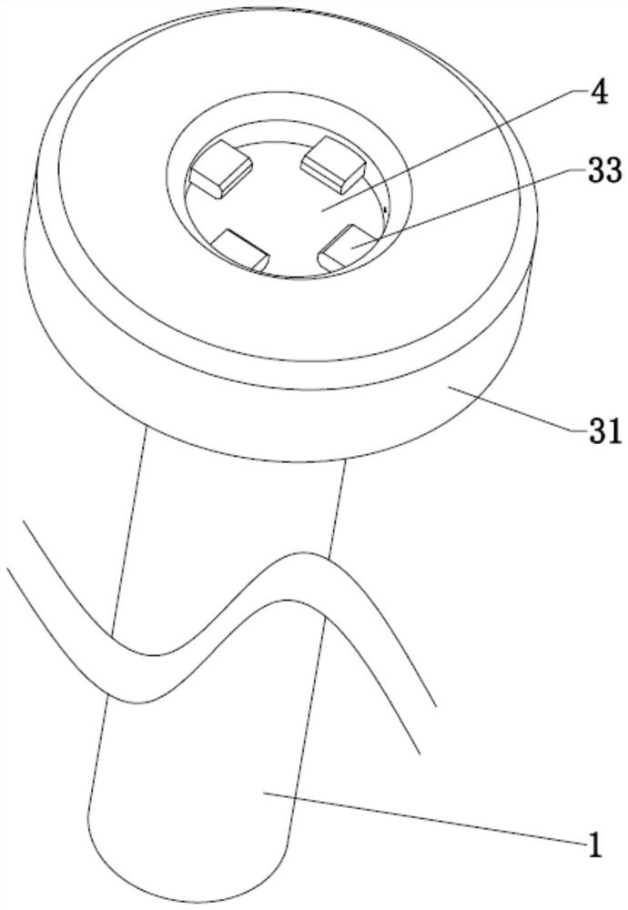
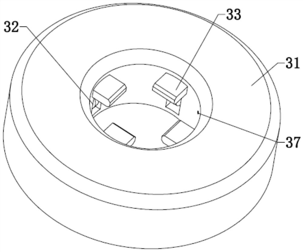
The invention relates to the technical field of wind driven generators, and discloses a wind driven generator with a lifting device. The wind driven generator comprises a stand column and an impeller,and further comprises the lifting device; the lifting device comprises a main body, a climbing part, a clamping part and a hanging part; a step for clamping the clamping part is arranged at the jointof the stand column and the impeller; the climbing part comprises rollers; the main body is provided with a forward and backward rotation motor for driving the rollers to roll to drive the main bodyto vertically move on the stand column; the clamping part comprises clamping strips; the wind driven generator further comprises a driving mechanism for driving the clamping strips to be movably inserted into the step; and the hanging part comprises a fixing shaft which is fixedly connected with the main body. According to the wind driven generator, through the technical scheme that the lifting device drives equipment or an operator to move to the position above the wind driven generator, the problems that in the prior art, the ladder climbing work intensity of the operator is high, and dailymaintenance of a wind driven generator is not convenient are solved, the operator can perform daily maintenance on the wind driven generator conveniently, and the lifting safety is relatively high.

Description

technical field [0001] The invention relates to the technical field of wind power generators, in particular to a wind power generator equipped with lifting equipment. Background technique [0002] A wind turbine is a power device that converts wind energy into mechanical work, which drives the rotor to rotate, and finally outputs alternating current. Wind turbines are generally composed of components such as wind rotors, generators (including devices), steering devices (tail fins), towers, speed-limiting safety mechanisms, and energy storage devices. [0003] The working principle of a wind turbine is relatively simple. The wind rotor rotates under the action of the wind, which converts the kinetic energy of the wind into the mechanical energy of the wind rotor shaft, and the generator rotates to generate electricity under the drive of the wind rotor shaft. In a broad sense, wind energy is also solar energy, so it can also be said that a wind generator is a thermal energy u...

Claims


Application Information

Patent Timeline
Patent Type & Authority Applications(China)
IPC IPC(8): B66F11/00B66F17/00F03D9/25F03D80/50
CPCB66F11/00B66F17/00F03D9/25F03D80/50Y02E10/72
Inventor 张国辉李广海刘岩马云龙安达万宝刘东旭
Owner HUANENG TONGLIAO WIND POWER CO LTD
Learn More