Compressor

A compressor and high-pressure side technology, applied in the field of compressors, can solve problems such as increasing the leakage of the working chamber, affecting the performance of the compressor, and the abnormal noise of the sliding vane

Active Publication Date: 2021-02-05
ZHUHAI GREE REFRIGERATION TECH CENT OF ENERGY SAVING & ENVIRONMENTAL PROTECTION
View PDF7 Cites 2 Cited by
  • Summary
  • Abstract
  • Description
  • Claims
  • Application Information

AI Technical Summary

Problems solved by technology

The detachment of the sliding vane will cause abnormal noise, and the leakage of the working chamber will increase when it is detached, which will affect the performance o

Method used


Image

  • Compressor
  • Compressor
  • Compressor

Examples


Embodiment Construction

[0030] The following will clearly and completely describe the technical solutions in the embodiments of the present invention with reference to the drawings in the embodiments of the present invention. Apparently, the described embodiments are only some of the embodiments of the present invention, but not all of them. The following description of at least one exemplary embodiment is merely illustrative in nature and in no way taken as limiting the invention, its application or uses. Based on the embodiments of the present invention, all other embodiments obtained by persons of ordinary skill in the art without creative efforts fall within the protection scope of the present invention.

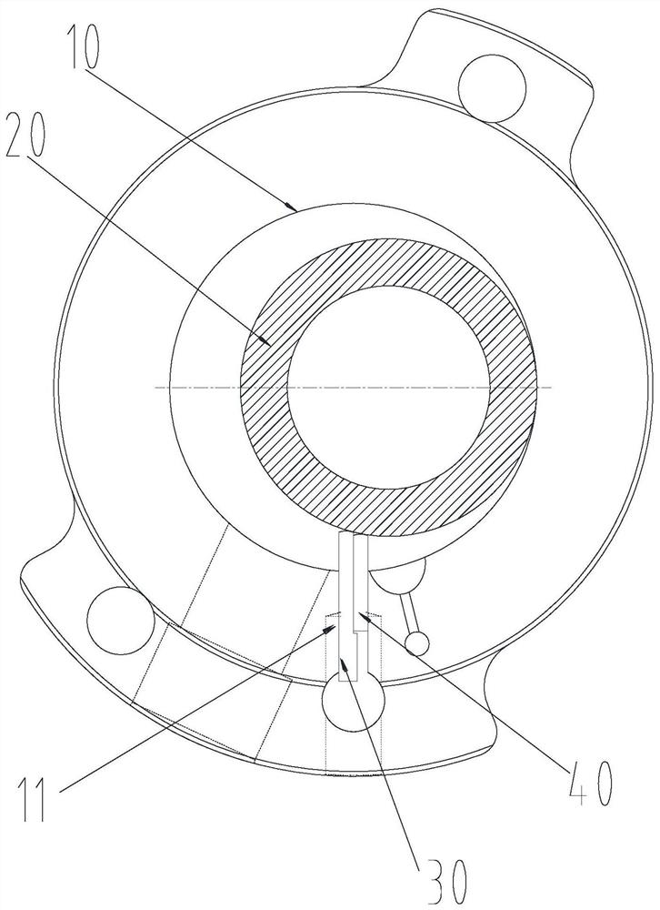
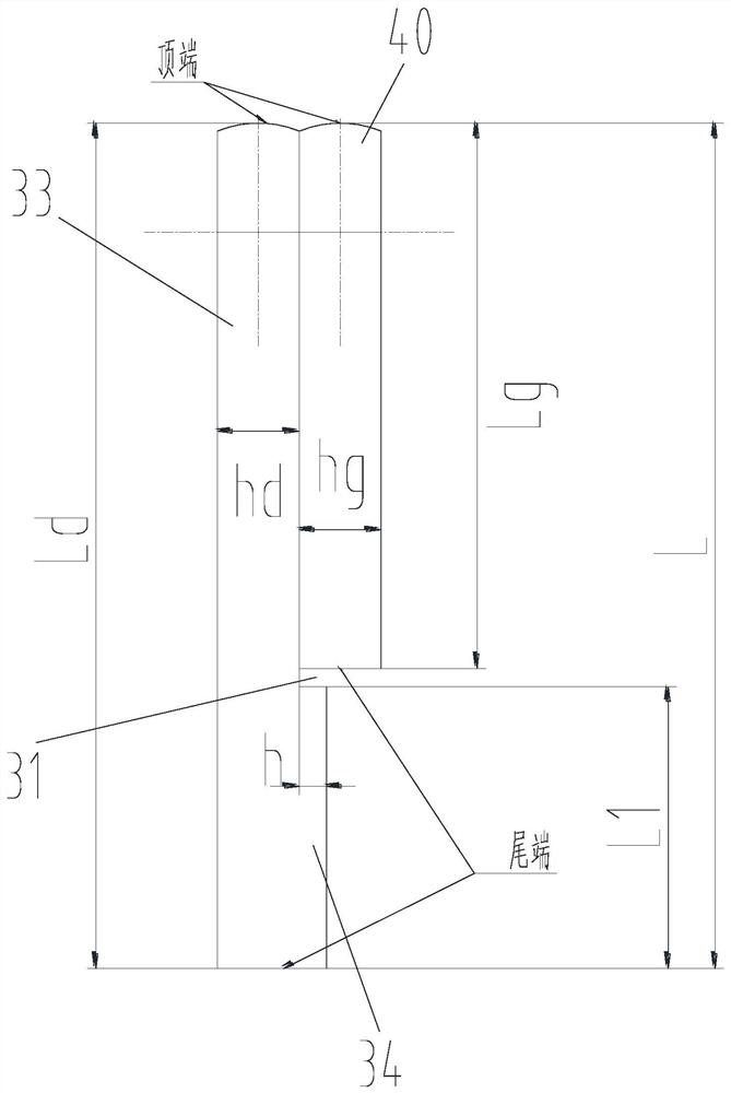
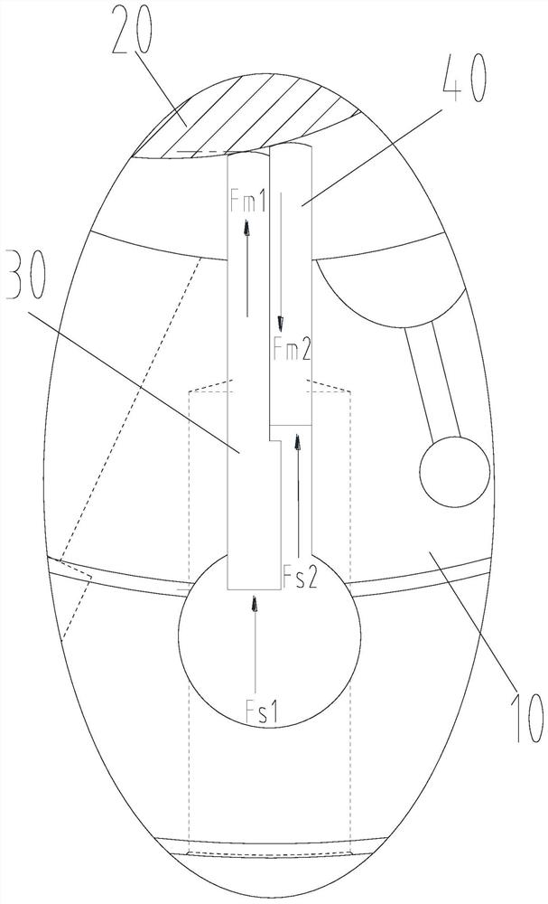
[0031] Such as Figure 1 to Figure 11 As shown, the embodiment of the present invention provides a compressor, including: cylinder 10; roller 20, rotatably arranged in the cavity of cylinder 10; slide group, slidably arranged in the slide groove of cylinder 10 11, the vane group includes a lo...


PUM


Abstract

The invention provides a compressor. The compressor comprises an air cylinder, a roller and a sliding piece set, wherein the roller is rotationally arranged in a cavity of the air cylinder; the sliding piece set is arranged in a sliding piece groove of the air cylinder in a sliding manner; the sliding piece set comprises a low-pressure side sliding piece and a high-pressure side sliding piece; anair suction cavity is formed by the area among the low-pressure side sliding piece, the roller and the inner wall of the air cylinder; a compression cavity is formed by the area among the high-pressure side sliding piece, the roller and the inner wall of the air cylinder; the low-pressure side sliding piece is provided with a limiting groove; the limiting groove is provided with a first side wallarranged in the axial direction of the sliding piece groove and a second side wall arranged in the radial direction of the sliding piece groove; and the side wall of the high-pressure side sliding piece is in limiting fit with the first side wall, and the tail end of the high-pressure side sliding piece is in limiting fit with the second side wall. By the adoption of the scheme, the problem of sliding piece disengaging can be solved, leakage is reduced, and the performance of the compressor is improved.

Description

technical field [0001] The present invention relates to the technical field of compressors, in particular to a compressor. Background technique [0002] Existing rotary compressors generally use a single vane, and rely on the pushing pressure of the spring to make the end of the vane tightly pressed against the outer surface of the roller, and the vane and roller divide the cavity in the cylinder into suction The air cavity and the compression cavity use the rotation of the crankshaft to drive the rollers to move, while the sliding plate reciprocates, and the cylinder repeatedly performs the suction, compression and discharge of gas to complete the basic functions of the compressor. However, because the sliding vane is in line contact with the outer circle of the roller, the top of the sliding vane is prone to wear under the force of the spring and the pressure difference, especially when the operating speed of the compressor is getting higher and higher, the wear is more ob...

Claims


Application Information

Patent Timeline
IPC IPC(8): F04C18/356F04C29/00
CPCF04C18/3562F04C29/00
Inventor 魏会军周瑜阙沛祯聂军王浩崔雪梅
Owner ZHUHAI GREE REFRIGERATION TECH CENT OF ENERGY SAVING & ENVIRONMENTAL PROTECTION
Why Eureka
Try Eureka