Reversing valve detection device

A detection device and reversing valve technology, which is applied in fluid pressure actuating devices, fluid pressure actuating system testing, mechanical equipment, etc., can solve problems such as low efficiency, internal structure damage and slowness of reversing valves, and achieve simple structure , easy to implement and convenient to use

Pending Publication Date: 2021-02-05
河北高达智能装备股份有限公司
View PDF0 Cites 0 Cited by
  • Summary
  • Abstract
  • Description
  • Claims
  • Application Information

AI Technical Summary

Problems solved by technology

[0003] 1. The reversing valve cannot be reversing or the reversing is slow due to damage to the valve core, jamming and burning of the coil, resulting in the failure of the liquid flow or air flow to flow in the predetermined direction;
[0004] 2. Due to the wear of the sealing ring of the valve core, the damage of the valve stem and the valve seat, the gas or liquid in the valve leaks, and the power required for the subsequent device action cannot be reached.
[0005] Most of the damage to the reversing valve is due to damage to the internal structure, and it is not easy to disassemble and cannot be identified with the naked eye
The traditional reversing valve detection method is mostly manually performed one by one, which is inefficient
In addition, it is also possible to make an automatic control system, which uses a controller to automatically detect the reversing valve, but most of them need programming to realize, and various control components are required, and the cost is relatively high

Method used


Image

  • Reversing valve detection device

Examples


Embodiment Construction

[0020] In order to facilitate those skilled in the art to understand the technical solution of this patent, the technical solution of this patent will be further described in the form of specific cases below.

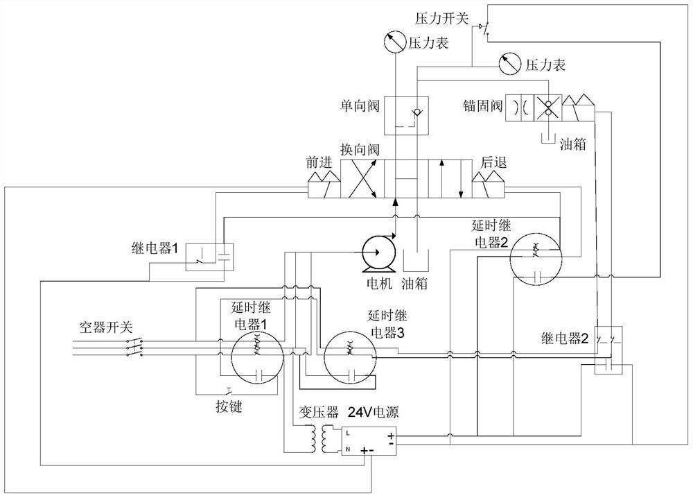
[0021] Such as figure 1 As shown, a reversing valve detection device includes a test oil circuit and a control circuit. The test oil circuit includes an oil pump arranged at the inlet end of the reversing valve, and a check valve arranged on two oil circuits at the outlet end of the reversing valve. , when the reversing valve retreats, the oil circuit opened when the reversing valve passes through the one-way valve is also connected with the anchor valve; the control circuit includes delay relays 1-3, normally closed relays 1-2, DC power supply, pressure switch, motor of the oil pump, Anchor valve electromagnet and ports for connecting the forward and reverse electromagnets of the reversing valve; wherein, the motor, DC power supply, anchor valve electromagnet and delay...


PUM


Abstract

The invention discloses a reversing valve detection device, and belongs to the technical field of detection tools. The reversing valve detection device comprises a test oil circuit and a control circuit, wherein the test oil circuit comprises an oil pump, a one-way valve and an anchoring valve, the control circuit comprises time-delay relays, normally-closed relays, a direct-current power supply,a pressure switch, a motor of the oil pump, an anchoring valve electromagnet and a port used for being connected with a reversing valve advancing electromagnet and a reversing valve retreating electromagnet, power supply branches of the motor, the direct-current power supply and a third time-delay relay are all controlled by a first time-delay relay, a power supply branch of the anchoring valve electromagnet is controlled by the third time-delay relay and a second normally-closed relay, a power supply branch of the advancing electromagnet is controlled by a first normally-closed relay, a powersupply branch of the retreating electromagnet is controlled by a second time-delay relay, and when the reversing valve advances, the power supply branches of the first normally-closed relay and the second time-delay relay are conducted. The reversing valve detection device does not need a controller, realizes automatic detection only through a circuit and a mechanical structure, can realize one-key automatic detection, and is very convenient to use.

Description

technical field [0001] The invention relates to a detection device for a reversing valve, which belongs to the technical field of detection tooling. Background technique [0002] The reversing valve is a valve that uses the difference in the relative position between the spool and the valve body to change the on-off relationship between different pipelines, realize connection and cut-off, and change the direction of liquid flow or air flow. It has a wide range of uses and is widely used in various fields of production. With the improvement of electromagnetic control technology and manufacturing process, solenoid valve can achieve more delicate control, and play its role in realizing different pneumatic systems and hydraulic systems. However, in actual use, the reversing valve is prone to problems. The common faults and the resulting results are as follows: [0003] 1. The reversing valve cannot be reversing or the reversing is slow due to damage to the valve core, jamming ...

Claims


Application Information

Patent Timeline
IPC IPC(8): F15B19/00
CPCF15B19/00
Inventor 谷龙飞张卫民
Owner 河北高达智能装备股份有限公司
Why Eureka
Try Eureka