Speed-change mechanism of variable-speed transmission

A technology of speed change mechanism and transmission, which is applied in the field of speed change transmission mechanism and speed change transmission, which can solve the problems of short service life, achieve long service life, avoid damage and improve reliability

Pending Publication Date: 2021-02-05
玉环县东方汽车制动器厂
View PDF2 Cites 4 Cited by
  • Summary
  • Abstract
  • Description
  • Claims
  • Application Information

AI Technical Summary

Problems solved by technology

[0004] The purpose of the present invention is to address the above problems in the prior art, and propose a speed change mechanism for a variable speed transmission, which solves the problem of short service life

Method used


Image

  • Speed-change mechanism of variable-speed transmission
  • Speed-change mechanism of variable-speed transmission
  • Speed-change mechanism of variable-speed transmission

Examples


Embodiment 1

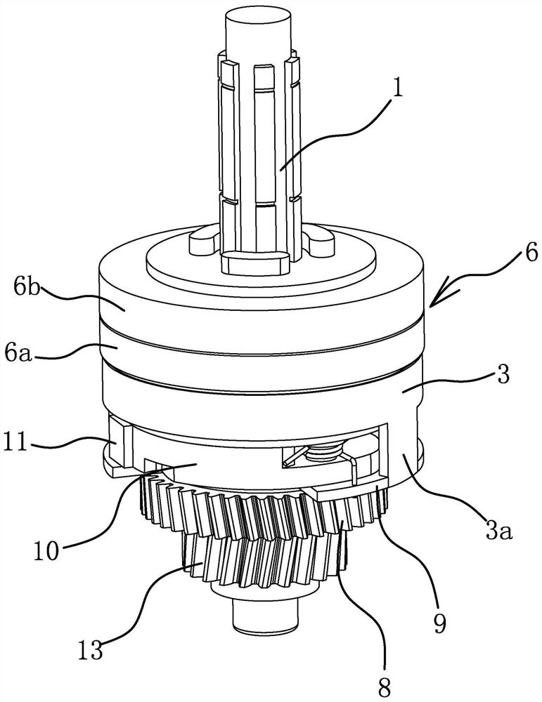
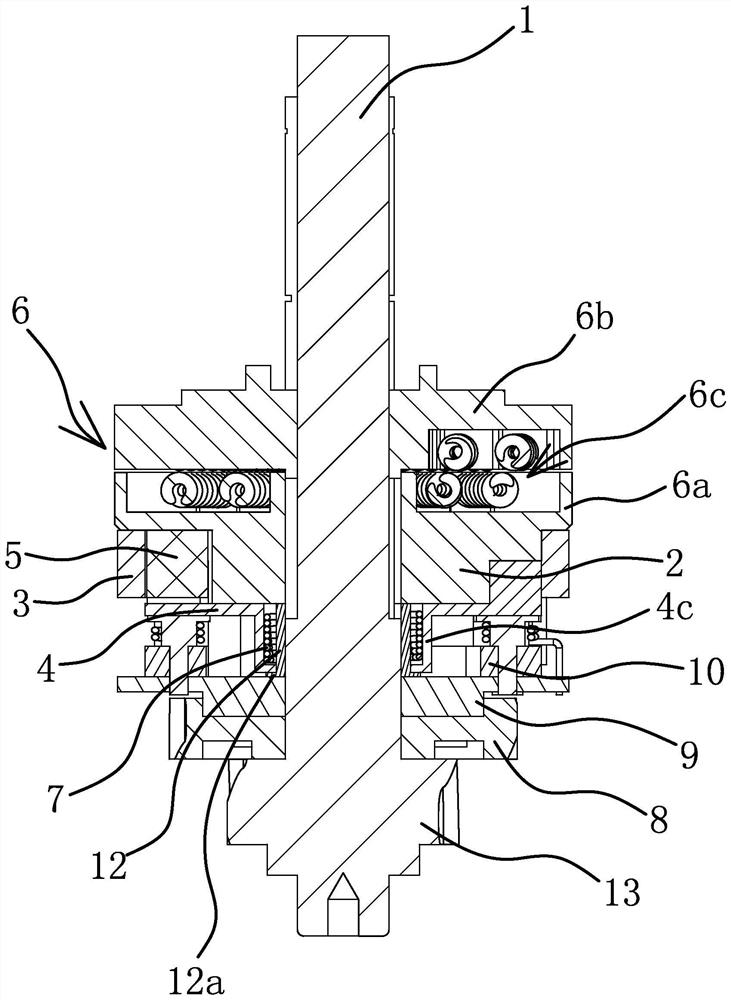
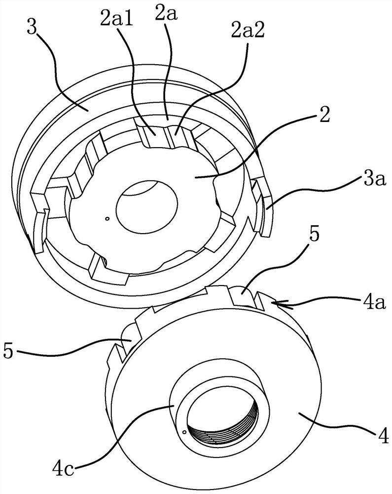
[0038] Such as Figure 1-Figure 4 As shown, the speed change mechanism of the variable speed transmission includes a main shaft 1, an inner ring 2 sleeved on the main shaft 1 and forming a linkage relationship with the main shaft 1, and an outer ring 3 axially fixed outside the inner ring 2 and capable of relative rotation. 1 is also sleeved with a rotatable control panel 4, and a clutch structure is provided between the outer ring 3 and the control panel 4. Between the outer ring 3 and the inner ring 2 there is a roller 5 controlled by the control disc 4, the outer side of the inner ring 2 has a movable groove 2a, the roller 5 is located in the movable groove 2a, when the control disc 4 rotates relative to the inner ring 2, it can The roller 5 is driven to move along the movable groove 2a so that the outer ring 3 and the inner ring 2 are linked or disengaged along the circumferential direction. The bottom wall of the movable groove 2a includes a relief surface 2a1 and a wedg...

Embodiment 2

[0048] The structure and principle of this embodiment are basically the same as those of Embodiment 1, except that in this embodiment, the wedging surface 2a2 is an oblique straight surface, and an obtuse angle is formed between the wedging surface 2a2 and the relief surface 2a1 horn.

Embodiment 3

[0050] The structure and principle of this embodiment are basically the same as that of Embodiment 1, the difference is that in this embodiment, the movable groove is arranged on the inner wall of the outer ring 3, and the wedging surface faces the direction closer to the outer wall of the inner ring 2 relative to the abdication surface. Tilt setting.


PUM


Abstract

The invention provides a speed-change mechanism of a variable-speed transmission, which belongs to the technical field of speed-change devices and solves the problem that the service life is short. The speed-change mechanism of the variable-speed transmission comprises a main shaft, an inner ring which sleeves the main shaft and defines a linkage relation with the main shaft, and a outer ring which is axially fixed outside the inner ring; a control disc capable of rotating further sleeves the main shaft; a clutch structure capable of enabling the outer ring and the control disc to link in theperipheral direction is further arranged between the outer ring and the control disc; a movable slot is formed outside the inner ring; a rolling column is arranged in the movable slot; while the control disc rotates relative to the inner ring, the rolling column can be driven to move along the movable slot, so that the outer ring and the inner ring are linked or separated in the peripheral direction; and the rolling column can freely rotate relative to the control disc. The speed-change mechanism further comprises an elastic return part; under action of elastic force of the elastic return part, the control disc has the trend of driving the rolling column to move in a separating direction in the peripheral direction of the outer ring and the inner ring. The speed-change mechanism of the variable-speed transmission has the advantages of being high in structural strength, strong in load ability, long in service life and the like.

Description

technical field [0001] The invention belongs to the technical field of speed change devices, and relates to a speed change transmission, in particular to a speed change mechanism of the speed change transmission. Background technique [0002] Automatic transmission is used in electric vehicles, which can realize the electric vehicle from low speed to high speed, and some can even switch the electric vehicle from the forward state to the reverse state. For example, the patent application number 201911101094.0 proposed by the applicant is a transmission mechanism for a two-way automatic transmission. Assemblies, the inner side of the rotating assembly is provided with connecting parts, and the transmission part is hinged with a number of coupling claws distributed around the main shaft. When the rotational speed of the rotating assembly is greater than the rotational speed of the main shaft, the connecting piece can be driven to rotate, and the outer side of the connecting pi...

Claims


Application Information

Patent Timeline
Patent Type & Authority Applications(China)
IPC IPC(8): F16H3/24F16D41/066
CPCF16D41/066F16H3/24F16H2200/0021F16H2200/0034F16H2200/2033
Inventor 屠申富屠昌德
Owner 玉环县东方汽车制动器厂
Why Eureka
Try Eureka