Electrified automatic gas supplementing device for SF6 equipment
An automatic gas replenishment and SF6 technology, which is applied to mechanical equipment, equipment discharged from pressure vessels, fixed-capacity gas storage tanks, etc., can solve the problems of high work intensity, long distance from the headquarters, low inflation efficiency, etc., and reduce work The effect of improving strength, improving safety factor and improving work efficiency
- Summary
- Abstract
- Description
- Claims
- Application Information
AI Technical Summary
Problems solved by technology
Method used
Image
Examples
Embodiment 1
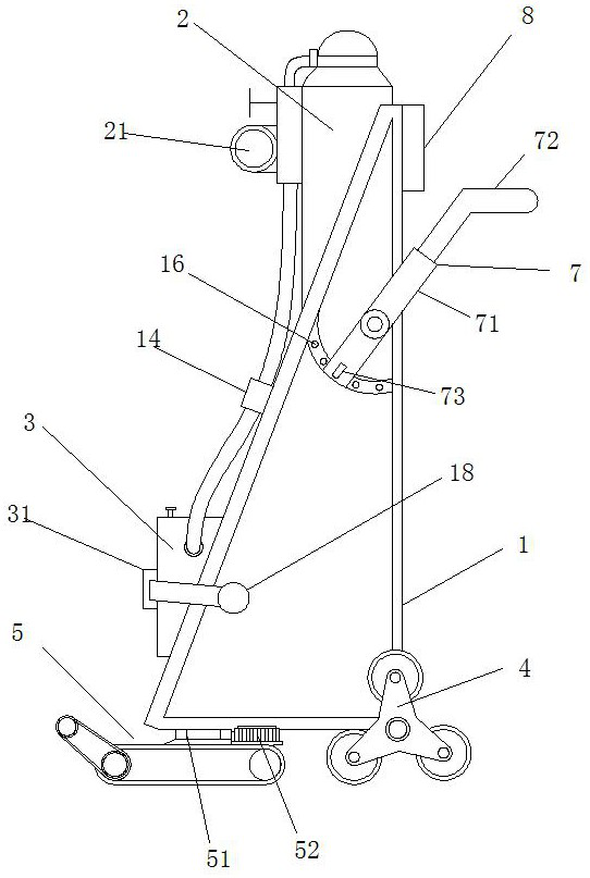
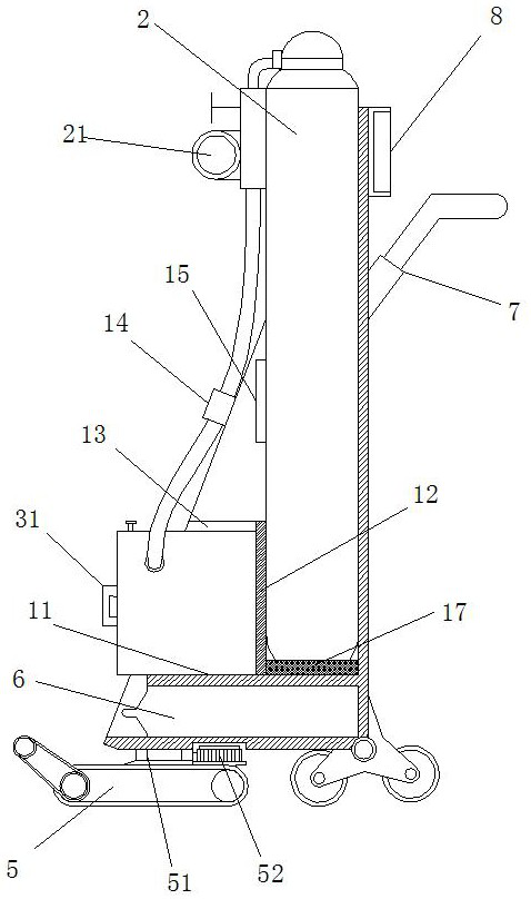
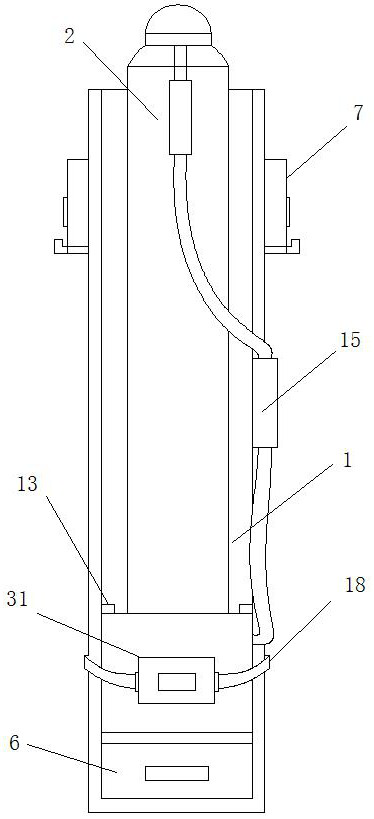
[0032] A charged automatic gas supply device for SF6 equipment, used to move gas cylinders 2 for gas supply; including a frame body 1, a gas supply device 3, a crawler mechanism 5, a power supply 6 with a handle, and a control panel 8; the frame body 1 is a triangular frame placed vertically, the hypotenuse of the frame body 1 is provided with an opening, and the inside is hollow; Insert the interlayer A of the power supply 6; the upper end of the middle part of the partition A11 is provided with a vertical partition B12, and the interlayer B for placing the bottom of the gas cylinder 2 is formed between the partition B12 and the side plate of the frame body 1; The front and rear wall panels of the frame body 1 are respectively provided with card slots 13, and the card slots 13, the partition board A11 and the partition board B12 form an interlayer C for installing the air supply device 3; The middle part of the frame body 1 is provided with a strap 15 for binding the middle p...
Embodiment 2
[0038] The difference from Embodiment 1 is that the push handle 7 includes a fixing part 71 and a U-shaped telescopic handle 72 installed at the front end of the fixing part 71; , the rear end of the fixing member 71 is provided with a spring bayonet 73; the frame body 1 is provided with a slot 16 matched with the spring bayonet 73, and the slot 16 is uniformly distributed in a ring shape for Adjust the angle of the U-shaped telescopic handle 72. The fixing piece 71 is used to adjust the angle, and the U-shaped telescopic handle 72 is used to adjust the length and distance, so as to adapt to workers of different physiques.
[0039] The working principle of this embodiment is the same as that of Embodiment 1.
Embodiment 3
[0041] The difference from Embodiment 1 lies in that the front and rear sides of the frame body 1 are respectively provided with fixing belts 18 , and the front end of the fixing belt 18 is provided with plugs.
[0042] The top of the box is provided with a handle; the left side of the box is provided with a buckle 31 matching the plug. The fixing belt 18 is inserted into the buckle 31 through the plug to achieve the effect of fixing the box body, and the handle is used for easy disassembly and assembly of the box body.
[0043] The working principle of this embodiment is the same as that of Embodiment 1.
PUM
 Abstract
Description
Claims
Application Information
 - R&D
- Intellectual Property
- Life Sciences
- Materials
- Tech Scout
- Unparalleled Data Quality
- Higher Quality Content
- 60% Fewer Hallucinations
Browse by: Latest US Patents, China's latest patents, Technical Efficacy Thesaurus, Application Domain, Technology Topic, Popular Technical Reports.
© 2025 PatSnap. All rights reserved.Legal|Privacy policy|Modern Slavery Act Transparency Statement|Sitemap|About US| Contact US: help@patsnap.com


