
Smelting device for mechanical equipment manufacturing

A technology for mechanical equipment and main body, which is applied in the field of smelting devices for mechanical equipment manufacturing, can solve the problems of increased energy consumption, increased production costs, and inability to utilize waste heat, and achieves the effects of preventing sealing and increasing energy consumption.

Pending Publication Date: 2021-02-05
湖州同奇机械设备有限公司
View PDF0 Cites 0 Cited by
  • Summary
  • Abstract
  • Description
  • Claims
  • Application Information

AI Technical Summary

Problems solved by technology

[0004] The object of the present invention is to provide a smelting device for mechanical equipment manufacturing to solve the problem that the existing device proposed in the above background technology is working, because the heating efficiency of the device is not high, and the waste heat cannot be used, which leads to problems in the process of production and processing. Increased energy consumption, however, during the heating process, the air pressure rises and cannot be released at any time, which leads to an increase in production costs

Method used

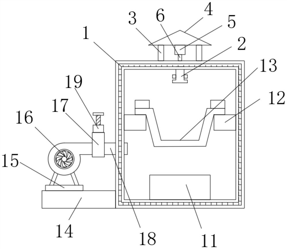

Image

  • Smelting device for mechanical equipment manufacturing
  • Smelting device for mechanical equipment manufacturing
  • Smelting device for mechanical equipment manufacturing

Examples


Embodiment Construction

[0020]The technical solutions in the embodiments of the present invention will be clearly and completely described below in conjunction with the accompanying drawings in the embodiments of the present invention. Obviously, the described embodiments are only a part of the embodiments of the present invention, rather than all the embodiments. Based on the embodiments of the present invention, all other embodiments obtained by those of ordinary skill in the art without creative work shall fall within the protection scope of the present invention.

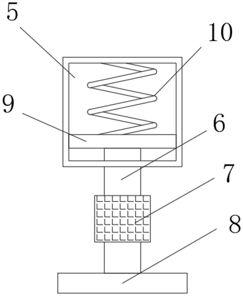
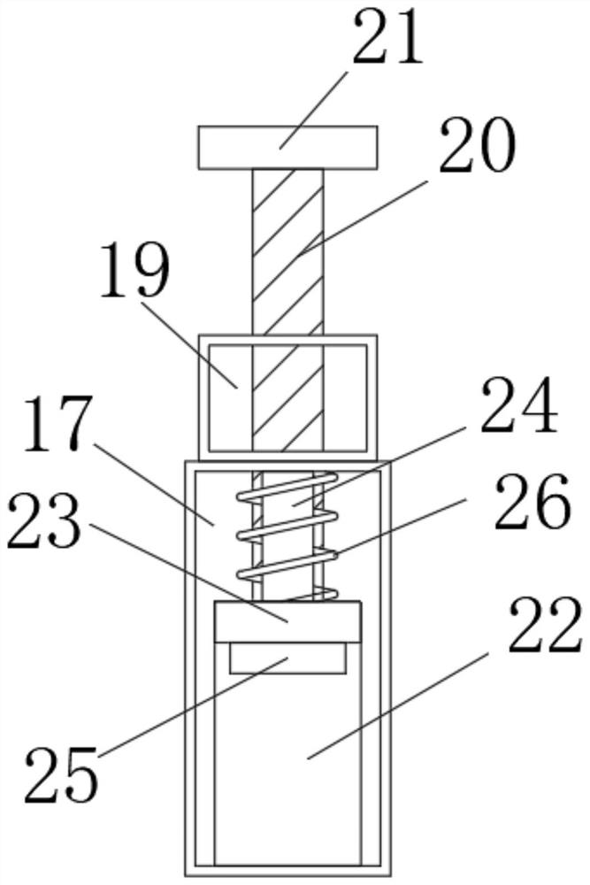
[0021]SeeFigure 1-4, The present invention provides a technical solution: a smelting device for mechanical equipment manufacturing, comprising a main body 1, the inner top of the main body 1 is fixedly connected with a first fixing block 2, and the top of the main body 1 is fixedly connected with a support rod 3, a support rod 3 A top cover 4 is fixedly connected to the top of the top cover 4, a connecting box 5 is fixedly connected to the bott...


PUM


Abstract

The invention discloses a smelting device for mechanical equipment manufacturing. The smelting device comprises a main body, wherein the top end of the interior of the main body is fixedly connected with a first fixing block, and the top of the main body is fixedly connected with a supporting rod; through the design of a connecting box, a moving rod, a sealing block, a pressed plate, a moving plate and a first spring, when the device works, air pressure can be generated in the heating process, when the air pressure reaches a certain degree, the pressed plate is jacked upwards, so that the pressed plate moves, the sealing block moves upwards from the top of the main body, the moving plate is driven to extrude the first spring, and as a result, the air pressure in the main body can be released; and when the release is completed, under the action of the first spring, the moving plate moves downwards, the moving rod, the sealing block and the pressed plate are driven to move downwards, themain body is sealed again, the waste heat is stored, and the problems that the waste heat cannot be utilized and the air pressure cannot be released at any time when the air pressure rises in the heating process are solved.

Description

Technical field[0001]The invention belongs to the technical field of mechanical smelting, and specifically relates to a smelting device for manufacturing mechanical equipment.Background technique[0002]Smelting is a pyrometallurgical process in which metal materials and other auxiliary materials are melted and tempered in a heating furnace. The charge undergoes certain physical and chemical changes in the high-temperature furnace to produce crude metal or metal enrichment and slag.[0003]When the existing device is working, the heating efficiency of the device is not high and the waste heat cannot be used, which leads to an increase in energy consumption during the production and processing. However, during the heating process, the pressure cannot be relieved at any time due to the increase in air pressure. Leading to the problem of increased production costs, we propose a melting device for mechanical equipment manufacturing.Summary of the invention[0004]The purpose of the present in...

Claims


Application Information

Patent Timeline
Patent Type & Authority Applications(China)
IPC IPC(8): F27B14/08F27D7/04F27D17/00
CPCF27B14/08F27D7/04F27D17/004F27M2003/13
Inventor 陈怀美
Owner 湖州同奇机械设备有限公司
Learn More