Screening machine screening strength real-time detection and analysis system
A real-time detection and analysis system technology, applied in the direction of material analysis, permeability/surface area analysis, machine/structural component testing, etc., can solve the problems of inability to detect sieving force in real time, lack of sieving force, adjustment, etc., to achieve convenience The effect of sieving force detection
- Summary
- Abstract
- Description
- Claims
- Application Information
AI Technical Summary
Problems solved by technology
Method used
Image

Examples
Embodiment 1
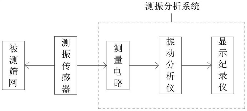
[0024] see figure 1 , an embodiment provided by the present invention: a real-time detection and analysis system for screening force of a screening machine, comprising a vibration measuring sensor, a measuring circuit, a vibration analyzer and a display recorder, and the vibration measuring sensor is fixed on a stationary support of the screening machine , the touch rod on the vibration sensor is consistent with the vibration direction of the screen to be tested, and is in contact with the surface of the screen to be tested by means of the elastic force of the spring. When the screen to be tested vibrates, the touch rod moves with the screen to be tested . The connection line of the vibration sensor is connected to the measurement circuit, the lead-out line of the measurement circuit is connected to the vibration analyzer, and then the lead-out line of the vibration analyzer is connected to the display recorder. The measuring circuit, the vibration analyzer and the display re...
Embodiment 2
[0026] An embodiment provided by the present invention: a real-time detection and analysis system for screening force of a screening machine, piezoelectric acceleration sensor: the mass block in the sensor generates displacement relative to the housing, the first conversion: input acceleration-relative displacement; The elastic force generated by the displacement is applied to the piezoelectric element, and charges with opposite polarities are generated on the two end faces of the piezoelectric element, and the second conversion: relative displacement-charge.
[0027] The relative method is used to calibrate the sensor: the bolt installation method uses the drilled thread to connect the piezoelectric acceleration sensor and the equipment. During testing and debugging, the sensors are connected together by bolts, and the tested screen is in the middle. Compare the performance of the two sensors. output, the sensitivity at that frequency.
[0028] The calibration work is carried...
Embodiment 3
[0030] An embodiment provided by the present invention: a real-time detection and analysis system for the screening force of a screening machine, the installation process:
[0031] S1. The vibration measuring sensor adopts a piezoelectric acceleration sensor. The vibration measuring sensor is fixed on the fixed support of the screening machine. Measuring screen surface contact;
[0032] S2. The measuring circuit uses the integrated circuit board as a carrier, the whole measuring circuit is installed in the junction box, the junction box is fixed on the screening machine, and the access end of the measuring circuit is connected to the vibration measuring sensor through wires;
[0033] S3. The vibration analyzer and display recorder are installed in the monitoring room. The access end of the vibration analyzer is electrically connected to the output end of the measurement circuit through wires, and the output end of the vibration analyzer is electrically connected to the input e...
PUM
 Abstract
Description
Claims
Application Information
PatSnap Eureka turns technology decisions into work you can execute. Powered by our Innovation Knowledge Graph, it runs expert workflows across engineering, life sciences, materials and intellectual property. Get your review-ready output in minutes.


