Waveguide optical fiber alignment coupling transmission structure and production process

A technology for optical fiber alignment and transmission structure, which is applied in the coupling of optical waveguides, light guides, optics, etc., can solve the problems of inability to carry out high-efficiency mass production, complicated process methods, and low production efficiency, so as to facilitate maintenance and repair , good connection reliability and extended service life

Active Publication Date: 2021-02-05
CHINA AVIATION OPTICAL-ELECTRICAL TECH CO LTD
View PDF11 Cites 4 Cited by
  • Summary
  • Abstract
  • Description
  • Claims
  • Application Information

AI Technical Summary

Problems solved by technology

[0002] For the optical waveguide interconnection of different layers of backplanes and the three-dimensional complex optical waveguide interconnection structure, the 3D direct writing technology based on the microfluidic dispensing machine is used to prepare the optical waveguide circuit; During coupling transmission, it is necessary to use a high-precision adjustment frame to debug and align the signal transmission fiber with the prepared waveguide. However, this method of debugging and alignment is complicated, the production efficiency is low, and the cost is high, so it cannot be mass-produced efficiently.

Method used


Image

  • Waveguide optical fiber alignment coupling transmission structure and production process
  • Waveguide optical fiber alignment coupling transmission structure and production process
  • Waveguide optical fiber alignment coupling transmission structure and production process

Examples


Embodiment 1

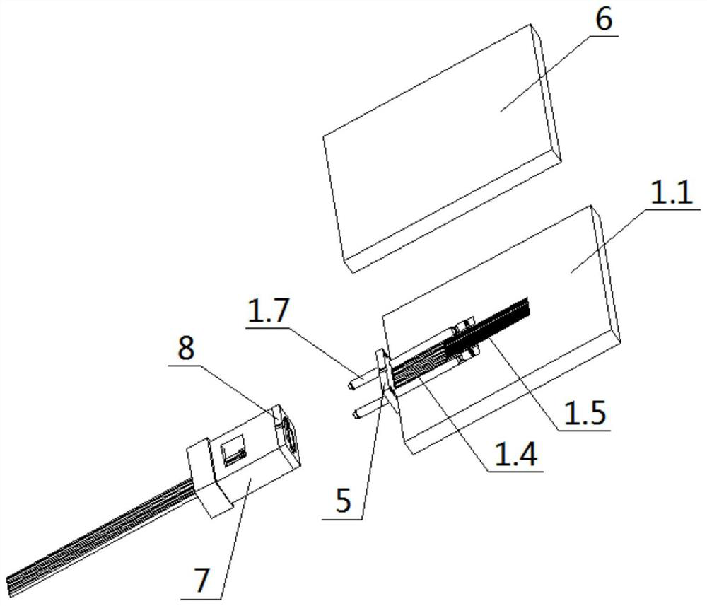
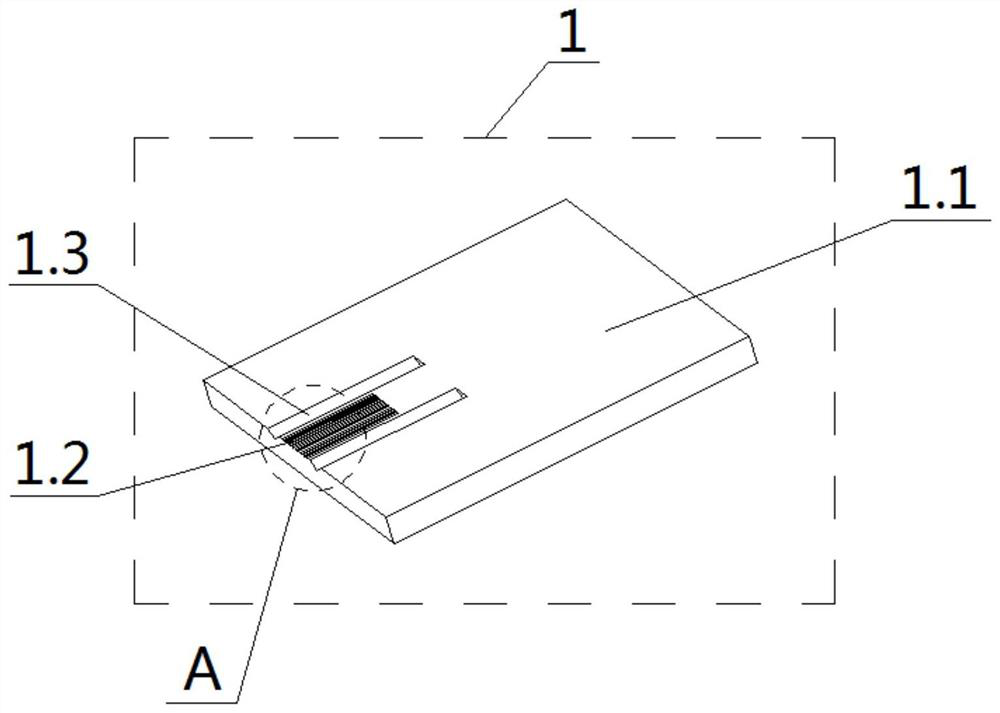
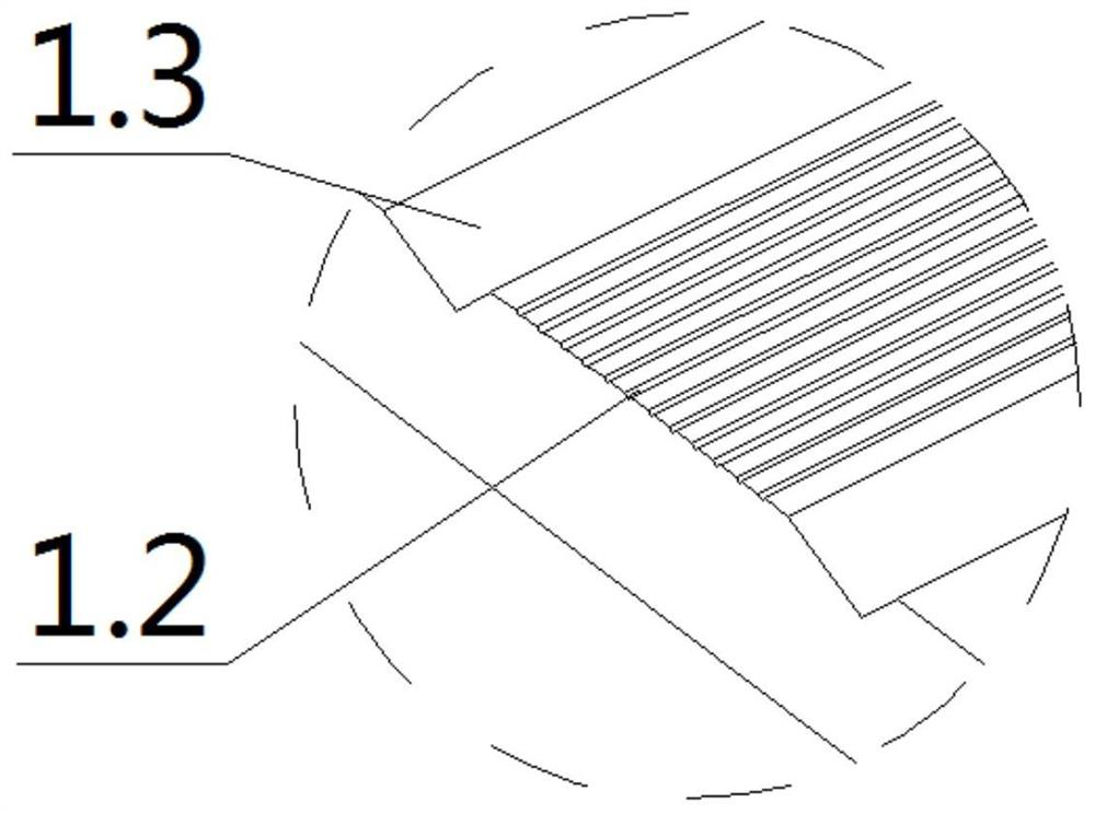
[0030] A waveguide alignment coupling transmission structure through an optical fiber, including an optical waveguide plate 1; the optical waveguide plate 1 includes an optical waveguide substrate 1.1, a hollow fiber 1.4, a waveguide 1.5, and a guide pin 1.7; the upper surface of the optical waveguide plate 1 is close to An array of pre-embedded optical fiber V-shaped grooves 1.2 is arranged on the edge of the board, and guide pin V-shaped grooves 1.3 are arranged on both sides of the embedded optical fiber V-shaped groove 1.2; one end of the hollow fiber 1.4 is a solid fiber segment 1.4.1, and the other end is a hollow The optical fiber section 1.4.2 has a circular cavity in the middle of the hollow optical fiber section 1.4.2; the hollow optical fiber 1.4 is fixed in the pre-embedded optical fiber V-shaped groove 1.2 with the solid optical fiber section 1.4.1 facing outward; the guide pin 1.7 Fixedly arranged in the guide pin V-shaped groove 1.3; the waveguide 1.5 is connecte...

Embodiment 2

[0032] A waveguide alignment coupling transmission structure through an optical fiber, including an optical waveguide plate 1; the optical waveguide plate 1 includes an optical waveguide substrate 1.1, a hollow fiber 1.4, a waveguide 1.5, and a guide pin 1.7; the upper surface of the optical waveguide plate 1 is close to An array of pre-embedded optical fiber V-shaped grooves 1.2 is arranged on the edge of the board, and guide pin V-shaped grooves 1.3 are arranged on both sides of the embedded optical fiber V-shaped groove 1.2; one end of the hollow fiber 1.4 is a solid fiber segment 1.4.1, and the other end is a hollow The optical fiber section 1.4.2 has a circular cavity in the middle of the hollow optical fiber section 1.4.2; the hollow optical fiber 1.4 is fixed in the pre-embedded optical fiber V-shaped groove 1.2 with the solid optical fiber section 1.4.1 facing outward; the guide pin 1.7 Fixedly arranged in the guide pin V-shaped groove 1.3; the waveguide 1.5 is connecte...


PUM


Abstract

The invention relates to a waveguide optical fiber alignment coupling transmission structure, which comprises an optical waveguide plate, a hollow optical fiber, a waveguide, a guide pin and a multi-core beam-expanding lens connector; the hollow optical fiber is fixedly arranged in a pre-embedded optical fiber V-shaped groove with a solid optical fiber section facing outwards; the guide pin is fixedly arranged in a guide pin V-shaped groove; the waveguide is connected with a hollow optical fiber section of the hollow optical fiber; a cladding is also arranged on the upper plate surface of theoptical waveguide plate and covers and wraps the hollow optical fiber and the waveguide; the multi-core beam-expanding lens connector is fixedly connected with the optical waveguide plate through guide pin positioning; through the pre-embedded optical fiber V-shaped groove and the guide pin V-shaped groove which are precisely machined in the optical waveguide plate at a time, the relative positionprecision of the hollow optical fiber and the guide pin after installation is guaranteed, therefore the optical fiber alignment precision of the hollow optical fiber and the MT optical connector is guaranteed when signals of the optical waveguide plate are mutually coupled and transmitted, the debugging alignment process link is omitted, the structure and the method have the advantages of high production efficiency and low cost, and meet the mass production requirements of interconnection of optical waveguides of different layers of backboards.

Description

technical field [0001] The invention relates to the technical field of optical waveguide plate signal coupling transmission, in particular to a waveguide through optical fiber alignment coupling transmission structure and production process. Background technique [0002] For the optical waveguide interconnection of different layers of backplanes and the three-dimensional complex optical waveguide interconnection structure, the 3D direct writing technology based on the microfluidic dispensing machine is used to prepare the optical waveguide circuit; During coupling transmission, it is necessary to use a high-precision adjustment frame to debug and align the signal transmission fiber with the prepared waveguide. However, this method of debugging and alignment is complicated, the production efficiency is low, and the cost is high, so it cannot be mass-produced efficiently. Contents of the invention [0003] In order to overcome the deficiencies in the background technology, t...

Claims


Application Information

Patent Timeline
Patent Type & Authority Applications(China)
IPC IPC(8): G02B6/36G02B6/032G02B6/122G02B6/32G02B6/38
CPCG02B6/3636G02B6/032G02B6/122G02B6/32G02B6/3897
Inventor 陈学永王莹韩道森张磊郭建设王楠楠
Owner CHINA AVIATION OPTICAL-ELECTRICAL TECH CO LTD
Why Eureka
Try Eureka