
Formation unmanned aerial vehicle multi-angle strike flight path planning method based on grid planning algorithm

A track planning and unmanned aerial vehicle technology, applied in three-dimensional position/channel control, vehicle position/route/altitude control, non-electric variable control, etc. Problems such as limited computing power

Active Publication Date: 2021-02-05
BEIJING INSTITUTE OF TECHNOLOGYGY
View PDF15 Cites 5 Cited by
  • Summary
  • Abstract
  • Description
  • Claims
  • Application Information

AI Technical Summary

Problems solved by technology

[0005] 1) The traditional manual calibration track method cannot meet the actual combat needs;
[0006] 2) During the planning process, the UAV formation is still in a state of motion, and the computing power of the onboard computer is limited, so it is difficult to quickly obtain a feasible trajectory through complex trajectory planning methods; resulting in low trajectory planning efficiency and long planning time , poor real-time performance;
[0007] 3) The result of trajectory planning does not meet the maneuverability constraints of the UAV, which makes the planned trajectory unrealizable in a complex environment and cannot effectively strike the target;
[0008] 4) The task environment is complex, and the communication link of the UAV formation may face enemy interference, and there are limitations such as packet loss and communication delay
The fully distributed system has good system scalability, but poor system coordination

Method used


Image

  • Formation unmanned aerial vehicle multi-angle strike flight path planning method based on grid planning algorithm
  • Formation unmanned aerial vehicle multi-angle strike flight path planning method based on grid planning algorithm
  • Formation unmanned aerial vehicle multi-angle strike flight path planning method based on grid planning algorithm

Examples


Embodiment

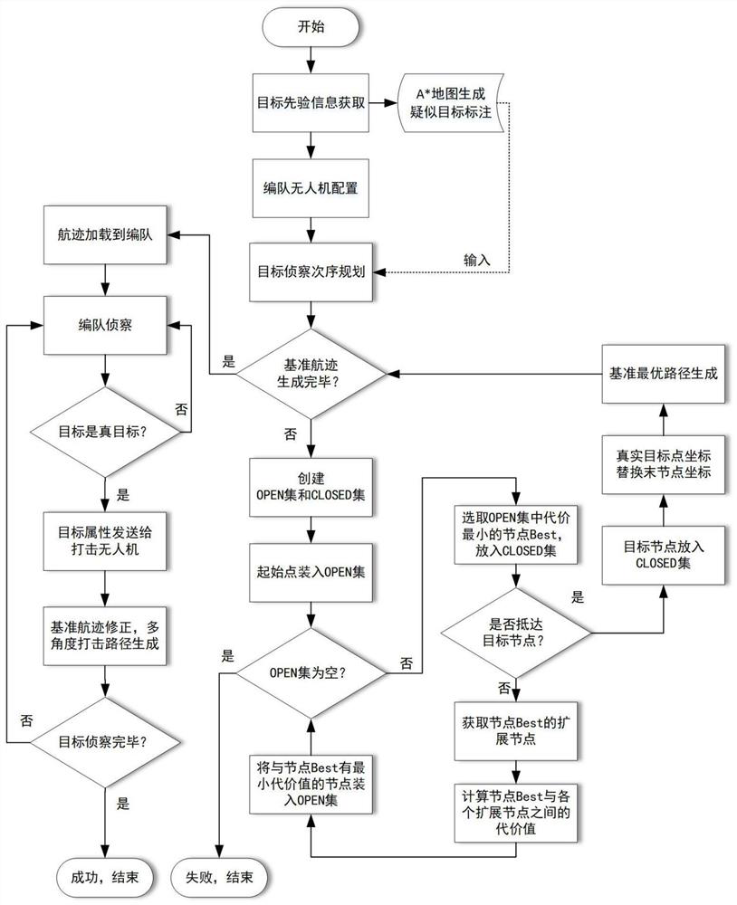
[0078]The flying speed of the UAV of this embodiment is 30m / s, the minimum turning radius is 150m, and the reconnaissance range of the reconnaissance load is 80m. In order to improve planning efficiency and make the path shortest, the grid planning algorithm is preferably the A* algorithm. Such asfigure 1 As shown, the method for multi-angle strike trajectory planning of formation drones based on grid planning algorithm disclosed in this embodiment includes the following steps:

[0079]Step 1: Obtain the prior information of the suspected target, design an A* map and mark the suspected target on the A* map.

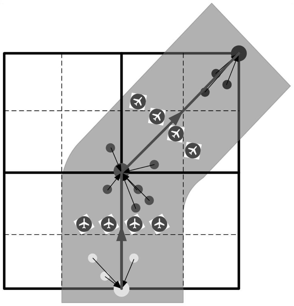
[0080]A*map grid uses a square grid, and the grid width is set to 2 times the turning radius of the drone, which is 300m. Set 4 suspected targets (unknown target value information at this time), the starting point of the formation drone is at the origin of the A* map coordinates, and the targets are integrated into the A* map node. Target coordinate integration methods such asfigure ...


PUM


Abstract

The invention discloses a formation unmanned aerial vehicle multi-angle strike flight path planning method based on a grid planning algorithm, and belongs to the technical field of flight path autonomous planning. The implementation method comprises the following steps of: explaining and modeling a scene and a problem which need to be planned, designing unmanned aerial vehicle formation members and formation forms, and formulating multi-angle striking schemes of targets with different values; performing position integration on a plurality of suspected targets, performing reconnaissance confirmation, and performing planning based on the grid planning algorithm to obtain flight paths of reconnaissance unmanned aerial vehicles in a formation; and expanding a planning result according to the value information of the targets to obtain a multi-angle strike flight path of the unmanned aerial vehicle formation. According to the method, rapid planning of the multi-angle strike flight path of the formation unmanned aerial vehicles is achieved based on the grid planning algorithm, the autonomous multi-angle strike flight path planning efficiency of the formation unmanned aerial vehicles can be improved, the formation unmanned aerial vehicles can execute multi-angle strike of different schemes on targets with different values; and the method has the advantages of being reliable in flight path point and easy to operate.

Description

Technical field[0001]The invention relates to a multi-angle strike trajectory planning method for formation drones based on a grid planning algorithm, which belongs to the technical field of autonomous trajectory planning.Background technique[0002]With the increasing complexity of the modern battlefield environment, UAVs have been more widely used than manned aircraft due to their low cost, flexible operations, diverse functions, and strong battlefield survivability, and are more suitable for performing dangerous tasks in harsh environments. The formation of multiple UAVs is one of the important ways of UAV collaboration, making the execution of tasks more flexible. UAV formations have a higher probability of damage to enemy targets from multiple angles, and are the mainstream trend and important role of future street fighting and air-to-ground operations. Driven by the demands of battlefield operations, UAV formation operations have gradually become a necessary capability for weapo...

Claims


Application Information

Patent Timeline
IPC IPC(8): G05D1/10
CPCG05D1/104
Inventor 刘莉葛佳昊贺云涛穆寒陆天和
Owner BEIJING INSTITUTE OF TECHNOLOGYGY
Learn More