
A dehumidifier for distribution box

A technology for distribution boxes and cooling devices, which is applied to circuit devices, substation/power distribution device casings, battery circuit devices, etc., can solve problems such as inability to dehumidify operation, non-compliance, high energy consumption, etc., to improve dehumidification effect and improve utilization efficiency and reduce energy consumption

Active Publication Date: 2022-07-01
江苏科腾环境科技有限公司
View PDF10 Cites 0 Cited by
  • Summary
  • Abstract
  • Description
  • Claims
  • Application Information

AI Technical Summary

Problems solved by technology

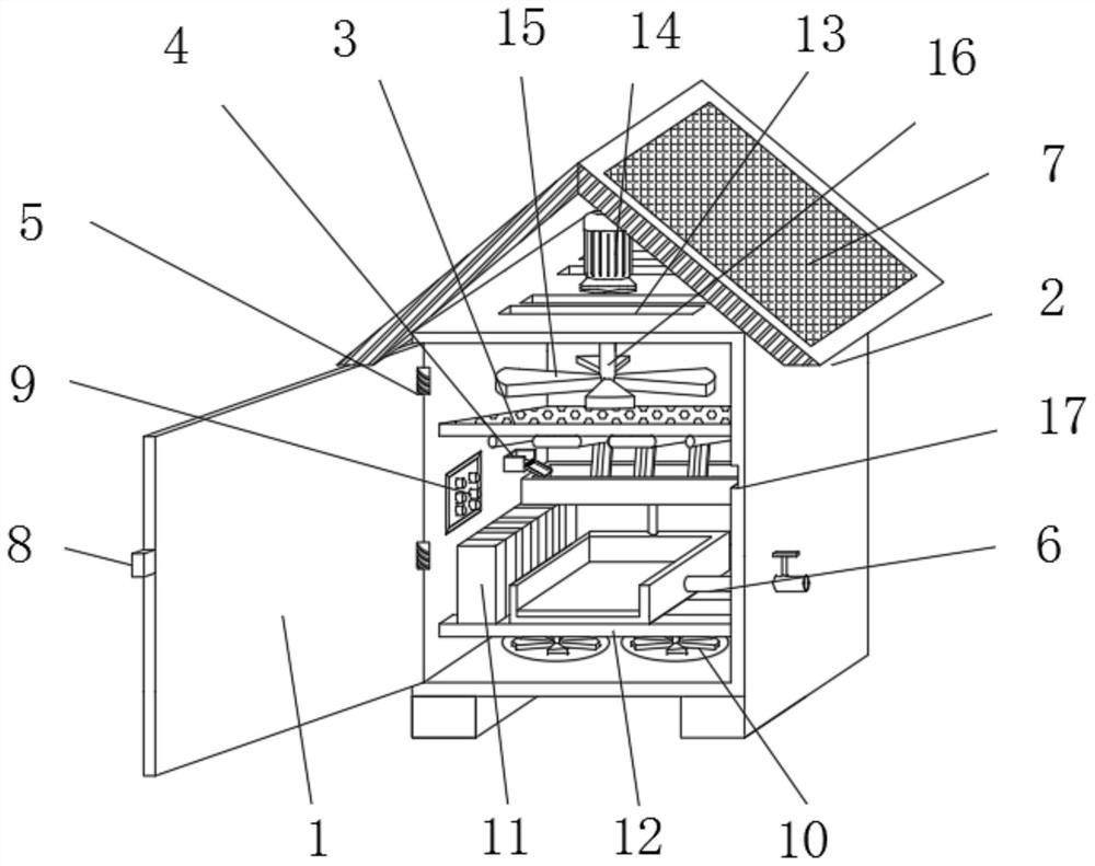
[0003] The existing patent (notification number: CN 107579435A) discloses a dehumidification device for terminal box, including terminal box, condensation dehumidification device, water guide plate, water storage tank, heating dehumidification device, power supply, lever and bracket, condensation dehumidification The device is arranged on the outside of the terminal box, and the outside of the terminal box is provided with a first through hole, and the condensation dehumidification device communicates with the first through hole. The inventors have found that at least the following problems have not been solved in the prior art: 1. The dehumidification device dehumidifies The method is single, and the dehumidification operation cannot be performed according to the moisture state, which makes the dehumidification effect poor; 2. The dehumidification device can only achieve a single dehumidification function, and the function is single, which does not meet the needs of modern dehumidification equipment; 3. The dehumidification device cannot be used for liquid Realize full utilization and high energy consumption, which does not conform to the modern concept of green development

Method used


Image

  • A dehumidifier for distribution box
  • A dehumidifier for distribution box
  • A dehumidifier for distribution box

Examples


Embodiment Construction

[0025] In order to make the technical means, creative features, achievement goals and effects realized by the present invention easy to understand, the present invention will be further described below with reference to the specific embodiments.

[0026] In the description of the present invention, it should be noted that the terms "upper", "lower", "inner", "outer", "front end", "rear end", "two ends", "one end" and "the other end" The orientation or positional relationship indicated by etc. is based on the orientation or positional relationship shown in the accompanying drawings, which is only for the convenience of describing the present invention and simplifying the description, rather than indicating or implying that the indicated device or element must have a specific orientation, a specific orientation, and a specific orientation. The orientation configuration and operation are therefore not to be construed as limiting the invention. Furthermore, the terms "first" and "...


PUM


Abstract

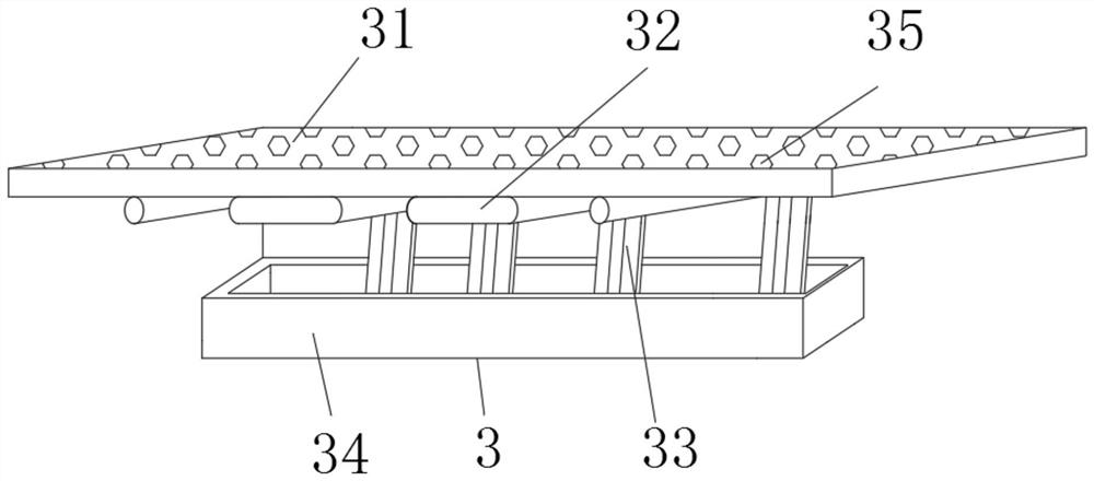
The invention discloses a dehumidification device for a power distribution box, comprising a case, two support rods are fixedly installed at the lower part of the case, a battery and a heat dissipation device are fixedly installed on the upper ends of the two support rods, and the upper part of the case is fixedly installed There is a dehumidifier, the lower end of the dehumidifier is fixedly connected to the upper end of the heat dissipation device, the middle part of the left end of the chassis is fixedly installed with a control box and a drying device, the right part of the drying device is fixedly connected to the left part of the dehumidifier, and the upper end of the chassis is left. The side and the right side of the upper end are fixedly installed with current collectors, and the upper end of the chassis is provided with a number of air exhaust holes. A dehumidification device for a distribution box according to the present invention has various dehumidification methods and can operate at the same time, thereby improving the dehumidification effect; in addition, the collected liquid can be heat-exchanged by the heat-dissipating device, so that the dehumidifying device has a heat-dissipating effect. , to meet the use requirements of modern dehumidification equipment; and the dehumidification device can improve the utilization rate of energy and reduce energy consumption.

Description

technical field [0001] The invention relates to the technical field of distribution boxes, in particular to a dehumidification device for distribution boxes. Background technique [0002] Distribution box refers to the functions of on-off, control or protection in the power generation, transmission, distribution, power conversion and consumption of the power system. The distribution box occupies a very important position in the entire power industry. In the process of using the box, it is often necessary to dehumidify the interior to avoid damage to the line. [0003] The existing patent (publication number: CN 107579435A) discloses a dehumidification device for a terminal box, including a terminal box, a condensation dehumidification device, a water guide plate, a water storage tank, a heating dehumidification device, a power supply, a lever and a bracket, and the condensation dehumidification device The device is arranged on the outside of the terminal box, the outside of...

Claims


Application Information

Patent Timeline
Patent Type & Authority Patents(China)
IPC IPC(8): H02B1/28H02B1/56H02B1/46H02J7/35B01D53/28B01D53/00
CPCH02B1/28H02B1/565H02B1/46H02J7/35B01D53/28B01D53/002B01D2257/80
Inventor 胡兴辉
Owner 江苏科腾环境科技有限公司
Learn More