A kind of waste gas treatment device and method for autonomous alternate filtering and cleaning
A waste gas treatment device and cleaning technology, applied in the direction of separation methods, dispersed particle filtration, chemical instruments and methods, etc., can solve the problems of reduced filtration efficiency and failure
- Summary
- Abstract
- Description
- Claims
- Application Information
AI Technical Summary
Problems solved by technology
Method used
Image
Examples
Embodiment 1
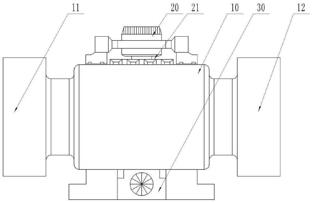
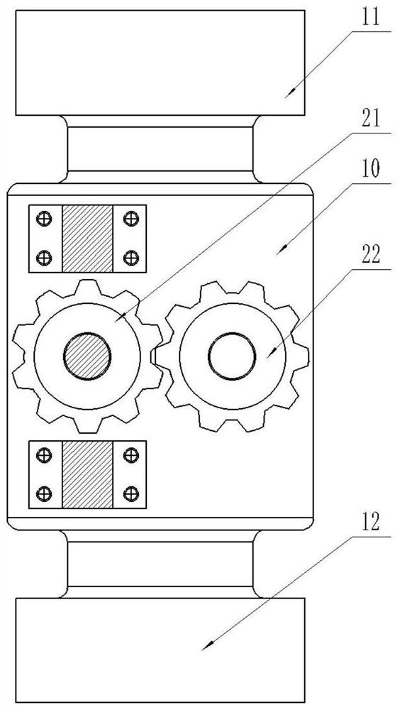
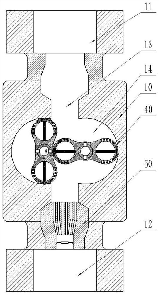
[0059] An exhaust gas treatment device for autonomous alternate filtering and cleaning, wherein, such as Figure 1-3 As shown, it includes: a casing 10 , a driving mechanism 20 , an air suction mechanism 30 , and a filtering mechanism 40 .
[0060] The housing 10 is made of rigid material, and the driving mechanism 20 is provided on the housing 10 . The driving mechanism 20 has a driving gear 21 and a driven gear 22 , and the driven gear 22 meshes with the driving gear 21 . The suction mechanism 30 is provided under the casing 10 .
[0061] The front and rear ends of the housing 10 have an air inlet 11 and an air outlet 12, an air passage 13 is arranged between the air inlet 11 and the air blowing port, the air inlet 11 and the air outlet 12 communicate with the air passage 13, and arcs are provided on both sides of the air passage 13. shaped movable cavity 14.
[0062] like image 3 , 4 As shown, the filter mechanism 40 has a swivel 41, the swivel 41 is respectively movab...
Embodiment 2
[0071] An exhaust gas treatment device for autonomous alternate filtering and cleaning, having the same characteristic structure as the first embodiment, wherein, such as Figure 9 As shown, a dehumidification mechanism 50 is provided at the air outlet 12 of the housing 10 .
[0072] The shunt channel 51 communicates with the air channel 13 , and a heating wire is provided around the shunt channel 51 . The shunt channel 51 communicates with the exhaust channel 52 at the lower end, and the exhaust channel 52 communicates with the air outlet 12 of the housing 10 . The exhaust channel 52 is provided with a vibrating membrane 53 , and the vibrating membrane 53 has elasticity.
[0073] After the exhaust gas is filtered, it is discharged from the ventilation channel 13, and the discharged gas enters the shunt channel 51 of the dehumidification mechanism 50 for shunt, and the heating wire in the shunt channel 51 heats the gas to remove moisture and bacteria in the gas. If it does no...
Embodiment 3
[0075] An exhaust gas treatment method for autonomous alternate filtering and cleaning, comprising the following steps:
[0076] Introduce the exhaust gas into the air inlet 11 of the housing 10, so that the exhaust gas enters the air passage 13;
[0077] The driving mechanism 20 is activated to drive the driving gear 21 to mesh with the driven gear 22 to rotate, and drive the filter mechanism 40 in the movable cavity 14 on both sides of the air passage 13 to rotate, so that the two rotating bodies 41 of the filter mechanism 40 rotate relative to each other, agitating the exhaust gas and causing the particulate matter in the exhaust gas to rotate. After a large amount of flow, the exhaust gas enters the filter chamber 42 along the ventilation hole 411 of the swivel 41, and the exhaust gas is filtered through the filter screen 43 in the filter chamber 42, so that the particulate matter in the exhaust gas adheres to the filter screen 43;
[0078] During the relative rotation of ...
PUM
 Abstract
Description
Claims
Application Information
 - R&D
- Intellectual Property
- Life Sciences
- Materials
- Tech Scout
- Unparalleled Data Quality
- Higher Quality Content
- 60% Fewer Hallucinations
Browse by: Latest US Patents, China's latest patents, Technical Efficacy Thesaurus, Application Domain, Technology Topic, Popular Technical Reports.
© 2025 PatSnap. All rights reserved.Legal|Privacy policy|Modern Slavery Act Transparency Statement|Sitemap|About US| Contact US: help@patsnap.com


