
Clamping tool for producing and welding computer component

A technology for clamping tooling and components, applied in welding equipment, auxiliary welding equipment, welding/cutting auxiliary equipment, etc., can solve the problems of complicated operation, unfavorable production efficiency, inability to rotate the circuit board, etc., to ensure safety and stable placement Effect

Inactive Publication Date: 2021-02-09
CHONGQING COLLEGE OF ELECTRONICS ENG
View PDF11 Cites 3 Cited by
  • Summary
  • Abstract
  • Description
  • Claims
  • Application Information

AI Technical Summary

Problems solved by technology

[0003] Most of the existing welding tooling is aimed at a certain circuit board, and its fixing method is relatively cumbersome. When a new circuit board needs to be processed, the welding tooling often needs to be replaced, which is not conducive to reducing the cost of the manufacturer. At the same time, the existing circuit board is welded The tooling cannot be rotated after it is fixed. If you want to solder the back of the circuit board or check the effect of the front side welding, you have to remove the circuit board from the welding tool for inspection. The operation is complicated and it is not conducive to improving production efficiency.

Method used


Image

  • Clamping tool for producing and welding computer component
  • Clamping tool for producing and welding computer component
  • Clamping tool for producing and welding computer component

Examples


Embodiment Construction

[0024] The technical solutions in the embodiments of the present invention will be clearly and completely described below in conjunction with the embodiments of the present invention. Apparently, the described embodiments are only some of the embodiments of the present invention, not all of them. Based on the embodiments of the present invention, all other embodiments obtained by persons of ordinary skill in the art without creative efforts fall within the protection scope of the present invention.

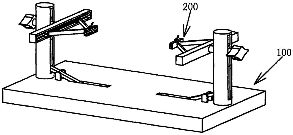
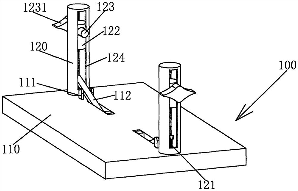
[0025] see Figure 1-6 As shown, a clamping tool for the production and welding of computer components includes a support mechanism 100 and a clamping mechanism 200. The support mechanism 100 includes a bottom plate 110 and a cylinder 120. The top surface of the bottom plate 110 is sequentially symmetrical about its vertical center plane. Two first rotating seats 111 and two cylinders 120 are fixedly connected, the middle part of the first rotating seat 111 is connected with a pre...


PUM


Abstract

The invention relates to the technical field of electronic machining, in particular to a clamping tool for producing and welding a computer component. The clamping tool comprises a supporting mechanism and a clamping mechanism, wherein the supporting mechanism comprises a bottom plate and cylinders, and the top surface of the bottom plate is sequentially, symmetrically and fixedly connected with two first rotating bases and two cylinders with the respective of the vertical central plane of the bottom plate. According to the clamping tool for producing and welding the computer component, one ends of pressing plates penetrate through arc-shaped notches, the bottom surfaces of the pressing plates are fixedly connected with one ends of reset springs, the other ends of the reset springs are fixedly connected with the bottom surfaces of inner cavities of the cylinders, the other ends of the pressing plates are fixedly connected with convex blocks, when sliding columns move downwards and makecontact with the pressing plates, the convex blocks make contact with the middle of the bottom surface of a circuit board, the circuit board can be placed stabler, when the circuit board needs to beturned over after the sliding columns ascend, the convex blocks move downwards into the bottom plate, and therefore the situation that the long sides of the circuit board abut against the convex blocks in a rotating process due to the fact that the width of the circuit board is larger is avoided, and safe and high-quality machining of the circuit board is guaranteed.

Description

technical field [0001] The invention relates to the technical field of electronic processing, in particular to a clamping tool used for production and welding of computer components. Background technique [0002] With the development of science and technology, the application of computer equipment is becoming more and more extensive. In the production process of computers, the welding work of computer circuit boards is the most important thing. First, the circuit boards are positioned and fixed, and then the electronic components Insert the two pins on the board into the pre-drilled holes on the circuit board, and solder the contact points between the pins and the front and back of the circuit board; [0003] Most of the existing welding tooling is aimed at a certain circuit board, and its fixing method is relatively cumbersome. When a new circuit board needs to be processed, the welding tooling often needs to be replaced, which is not conducive to reducing the cost of the m...

Claims


Application Information

Patent Timeline
Patent Type & Authority Applications(China)
IPC IPC(8): B23K3/08B23K37/04B23K101/42
CPCB23K3/087B23K2101/42
Inventor 余平何桂兰李红蕾胡云冰赵世丽朱正雄
Owner CHONGQING COLLEGE OF ELECTRONICS ENG
Learn More